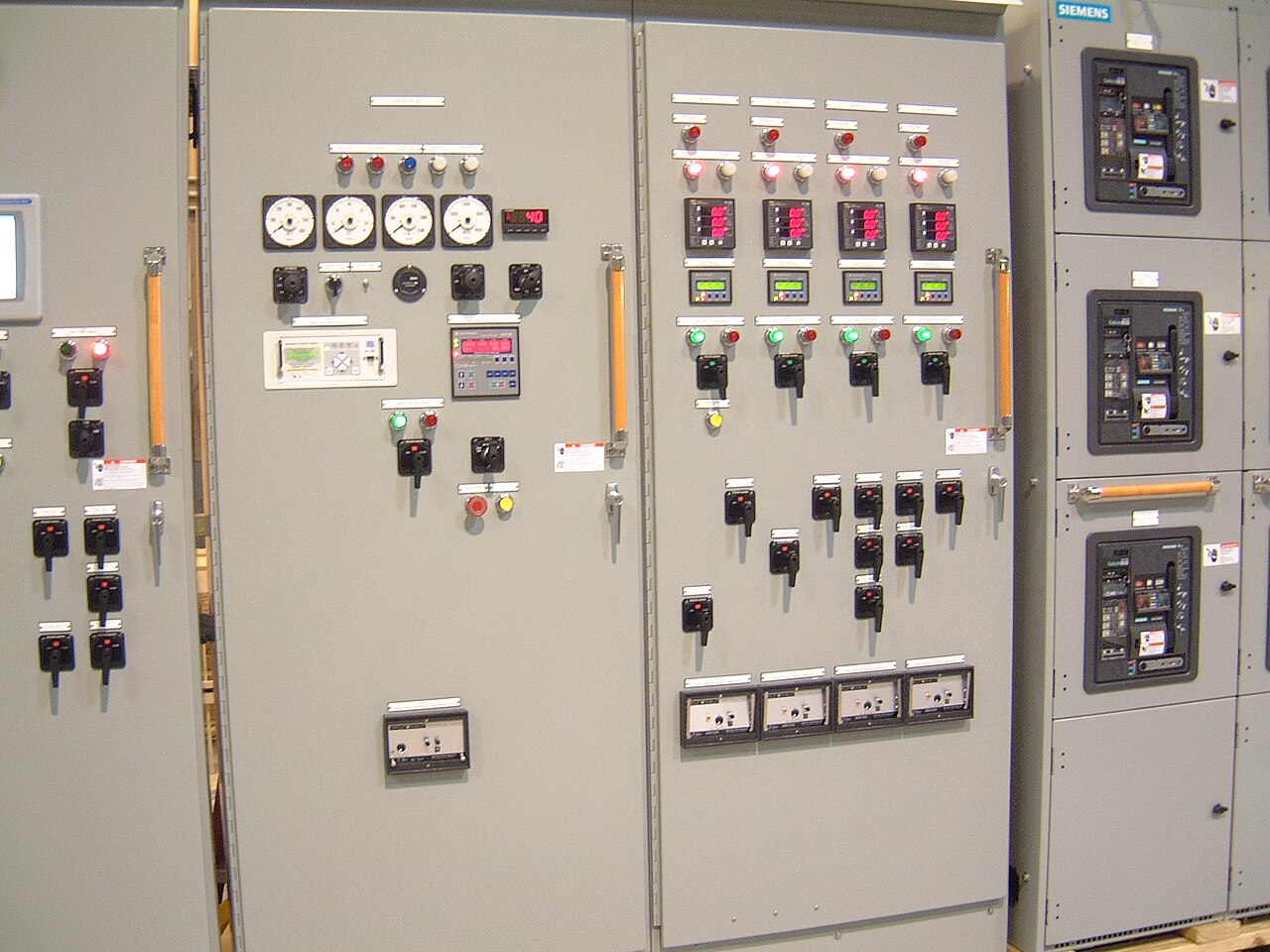
Power distribution, with purpose.
Switchgear manufacturing starts with the electrical duty the equipment must perform, not with a cabinet drawing. A well-defined path from project requirements to engineered design, shop assembly, and documented testing helps purchasers uncover interface conflicts before they become schedule or commissioning problems. For projects in Dallas–Fort Worth or elsewhere in the United States, provide the available system and site information early so the manufacturer can evaluate a practical new-equipment build.
Define the electrical duty before choosing an arrangement
Begin with the one-line diagram and identify the system’s nominal voltage, frequency, phase and wire arrangement, grounding method, and available fault current. State the equipment function—such as service entrance, distribution, transfer, or motor control—and identify the sources, loads, and operating sequence. Nominal system voltage is not the same as an assembly’s maximum rating; engineering must confirm suitable ratings for the specific design and application.
Also supply the required continuous current, short-circuit duty, protection approach, and any source coordination or selective-tripping objectives. A high interrupting rating alone does not establish that the complete assembly is suitable: bus bracing, protective devices, enclosure construction, and upstream conditions all matter. If fault-current or coordination data are preliminary, mark them as such rather than allowing an assumption to become a final design input.
Turn the one-line diagram into a buildable specification
A one-line diagram describes electrical relationships, but a quote and production design also need equipment-level detail. Provide the desired lineup arrangement, section functions, breaker or switch types, protective-device requirements, metering, control power, interlocks, and any communications or remote-monitoring interfaces. Identify which devices are owner-furnished and which are expected in the new assembly, since responsibility for procurement, fit, and integration should be clear before release.
Attach the latest drawing revision and note applicable project specifications, governing codes, and required standards. For low-voltage switchboards, UL 891 may be relevant, subject to confirmation for the particular assembly and order. It is not a general listing for medium-voltage switchgear. Voltage-class terminology, standards applicability, component availability, and any U.S.-origin requirements need order-specific review; do not infer them from a product name or a preliminary budget description.


Resolve site interfaces and physical constraints early
The electrical design must fit the building and connect to equipment around it. Furnish available room dimensions, access and removal paths, mounting conditions, cable-entry direction, conductor type and size, termination space, and the locations of incoming and outgoing connections. Clarify whether the installation uses top or bottom entry and whether the lineup must align with existing gear, transformers, generators, or distribution equipment. Incomplete interface information can drive late changes to section layout or cable provisions.
Environmental and operating conditions shape enclosure and accessory choices. Specify indoor or outdoor placement, ambient conditions, exposure concerns, service access, and any project requirements for barriers, heaters, ventilation, or enclosure protection. If the equipment serves a Dallas–Fort Worth project, share the actual site and delivery constraints rather than assuming a local manufacturing or installation presence. Shipping nationwide likewise makes route, unloading, and receiving arrangements useful planning inputs, not assumed capabilities.
Review the engineered design before shop release
After the requirements are reviewed, the design package should make the proposed arrangement understandable to the purchaser and project team. Review the one-line, elevations, section schedule, device details, connection points, control schematics, and terminal information against the specification. Confirm that breaker positions, metering, labels, interlocks, and control interfaces match the intended operating sequence. A drawing approval should resolve technical discrepancies, not simply acknowledge that a drawing was received.
Treat substitutions and open questions as explicit decision points. A requested component may have availability or compatibility constraints, and an alternate can affect dimensions, coordination, maintenance, or controls. Record accepted changes and identify any remaining assumptions before production authorization. Custom assembly can accommodate project-specific requirements, but a custom feature is not automatically included: the scope, design feasibility, ratings, and applicable standards must be confirmed for the particular order.
Build with controlled components and documented interfaces
Shop assembly translates approved engineering into a coordinated lineup. Buswork, protective devices, instrument transformers, control wiring, terminals, and mechanical structures must correspond to the released drawings and selected components. American components can be specified as a purchasing preference, but origin requirements should be stated precisely and verified for the actual bill of materials. Component availability and substitutions should be checked before they affect the planned production sequence.
Purchasers can reduce rework by supplying complete interface data and responding to drawing questions promptly. That includes confirming accessory selections, control-voltage expectations, external wiring responsibilities, and any customer-furnished devices. Shorter lead time may be a project goal, but it cannot be promised without reviewing the scope, component supply, design approvals, and shipping needs. A useful quote request therefore identifies required dates as planning targets and distinguishes firm requirements from preferences.
Use inspection and testing to close the manufacturing loop
Testing should be defined by the approved design, applicable requirements, and agreed order scope. Inspection may verify construction, wiring, labeling, and device installation against released documents; electrical checks may address continuity, control operation, and other specified functions. The exact test program depends on the assembly and must be agreed rather than assumed. Shop testing does not replace site acceptance, commissioning, or verification of field connections.
Before shipment, request clarity on what inspection and test records will be provided and how deviations are documented and resolved. Confirm the approved drawings, nameplate information, shipping configuration, and receiving requirements are aligned. For a quote, send the one-line diagram, equipment schedule, project specification, required ratings, site and cable-interface data, control details, applicable standards, delivery destination, and target schedule. This gives engineering a sound basis to identify gaps, evaluate a custom new-equipment build, and define what the order will include.
Specifications & planning
Review the details that matter for your application. Final specifications and availability should be confirmed for your project.
| Evaluation factor | Information to confirm |
|---|---|
| Electrical duty | Nominal voltage, continuous current, fault-current basis, and protection objectives |
| Assembly scope | Lineup functions, devices, controls, metering, and owner-furnished items |
| Physical interface | Room constraints, cable entry, terminations, environment, and receiving access |
| Verification | Applicable standards, agreed inspection and test scope, and records required |