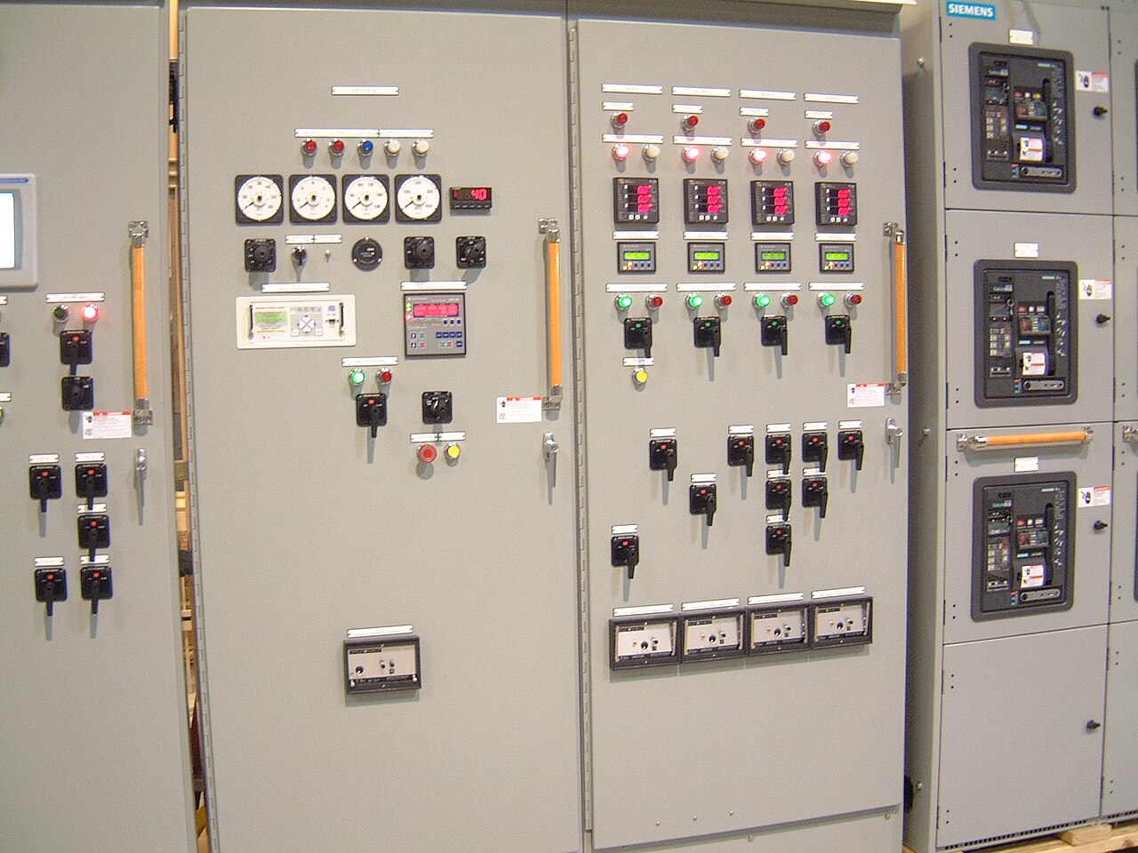
Power distribution, with purpose.
Power distribution equipment is a connected system, not a collection of interchangeable cabinets. Choosing the right product family starts with the electrical function at each point—from service entrance and feeder distribution to motor control and transformation—and continues through the interfaces between them. A useful equipment plan records how power enters, is protected, divided, measured, and delivered to downstream loads. That view helps purchasers define a coherent new-equipment package, expose coordination questions early, and avoid specifying components that cannot work together as intended.
Start with the function each lineup must perform
Switchboards, switchgear, panelboards, motor control centers, and transformers address different duties. A low-voltage switchboard commonly distributes power through a service or feeder arrangement; a panelboard organizes branch circuits; a motor control center groups motor-control units; and a transformer changes voltage between portions of a system. Medium-voltage switchgear serves distribution at a different voltage class and protection level. The one-line diagram should identify each function and its connection to the next, rather than using “switchgear” as a catch-all label.
For every lineup, state whether it is service entrance, distribution, transfer, tie, motor-control, or another defined application. Note the source and destination, normal operating configuration, and any alternate source or bypass path. These distinctions shape bus arrangement, switching and protection functions, compartment needs, and control interfaces. They also help establish whether a project needs one equipment family, several coordinated families, or a packaged combination.
Specify voltage, current, and fault duty as separate facts
Record the system’s nominal voltage and frequency, then separately identify the equipment voltage rating required for that system. Do not treat those values as interchangeable: a nominal system voltage describes the electrical network, while an equipment rating is a characteristic that must suit its application. The same care applies to current. Provide the expected continuous load and relevant demand information, but also identify the required bus and device ratings for engineering review.
Available fault current at the installation point is essential to equipment selection and coordination. Include the source contribution, transformer impedance where applicable, and any utility or consulting-engineer fault study available. Specify the required short-circuit rating and duration or other applicable basis from the project documents, without assuming that a familiar rating is suitable. Voltage class, current ratings, interrupting capability, and standards applicability must be confirmed for the specific order; 5 kV, 15 kV, 27 kV, and 35 kV are medium-voltage classes in this context, not UL 891 switchboard ratings.


Draw the interfaces, not just the equipment outlines
Interconnection records make a product package buildable. The one-line diagram should show source and feeder relationships, main and tie devices, transformer connections, grounding, metering, and protective-device locations. Add a schematic or control narrative for functions such as electrical interlocks, transfer logic, remote trip, alarms, and status points. Identify which signals are hardwired and which, if any, use a communications network, including the expected point names and protocol requirements.
Physical interfaces deserve the same attention. Provide incoming and outgoing cable or bus-duct entry locations, conductor quantities and sizes when established, termination preferences, neutral and ground arrangements, and the intended route between lineups. Include available room dimensions, access constraints, elevation, and the proposed equipment sequence. A mismatch in cable entry, phase orientation, bus connection, or control wiring can create field changes even when each individual device appears correctly rated.
Coordinate protection, metering, and operating intent
Protection requirements should reflect the system study and operating goals, not simply a list of preferred devices. Identify which circuits require overcurrent protection, ground-fault functions, differential protection, or other specified schemes, and provide the coordination study or its design criteria when available. State whether selective coordination, arc-energy reduction features, or zone-selective interlocking are required. These choices affect device selection, settings, wiring, and the information needed from upstream and downstream equipment.
Metering and controls should be defined by what operators need to observe or command. Specify measurements, accuracy requirements, local displays, remote monitoring points, alarm behavior, and control authority. Explain normal and emergency operating modes, including who is permitted to initiate a transfer or operate a tie. Where a project expects integration with a building or plant control system, identify the interface responsibilities and acceptance criteria. Final device ratings, settings, and functions remain subject to engineering review and order-specific confirmation.
Build a quote package around verifiable project inputs
A clear request for quote should include the latest one-line diagram, equipment schedules, applicable specifications, fault-current information, and the required delivery location. Add the number of sections or lineups, anticipated service conditions, indoor or outdoor application, enclosure expectations, cable-entry direction, and any dimensional limits. Mark open items rather than silently assuming them; unresolved utility data, future expansion, or an unapproved operating sequence can change the equipment scope.
Also identify required submittal documents, drawing review milestones, testing or inspection expectations, shipping constraints, and requested schedule. Customers in Dallas–Fort Worth and elsewhere should provide the actual site and receiving requirements rather than infer a local facility or delivery arrangement. The manufacturer builds and supplies new equipment, including custom configurations with American components where specified. A shorter lead time can be a goal, not a guarantee; component availability, standards, ratings, and any U.S.-origin requirements must be checked for the particular order.
Compare product packages by fit and evidence
When evaluating alternatives, compare each family against its stated duty and interfaces, not cabinet appearance or a single headline rating. Check that the proposed arrangement matches the one-line, operating sequence, space and access envelope, cable connections, control requirements, and system-study assumptions. For low-voltage switchboards, UL 891 may be applicable, but it is not a general listing for medium-voltage or high-voltage switchgear. Ask which standards and documentation apply to the exact assembly rather than assuming a standard from a product label.
Review exceptions and dependencies alongside the proposed scope: items requiring confirmation, owner-furnished devices, utility requirements, field connections, and coordination with other suppliers should be explicit. A disciplined comparison makes tradeoffs visible, such as reserving space for future feeders versus minimizing lineup length, or adding monitoring points versus simplifying controls. The final selection should be based on the purchaser’s approved electrical design and a documented engineering review of the complete equipment interfaces.
Specifications & planning
Review the details that matter for your application. Final specifications and availability should be confirmed for your project.
| Evaluation factor | Information to document |
|---|---|
| System basis | Nominal voltage, frequency, and equipment rating required; confirm for the order |
| Fault duty | Available fault-current study and required short-circuit rating; engineering review needed |
| Interconnections | One-line, cable or bus entry, grounding, control signals, and operating sequence |
| Project constraints | Dimensions, environment, shipping and receiving needs, submittals, and requested schedule |