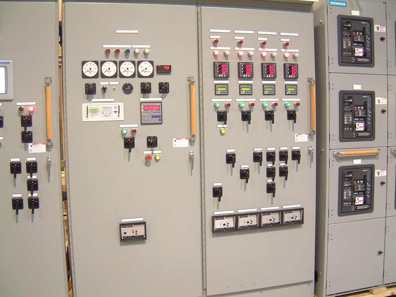
Power distribution, with purpose.
Busbar bracing is the mechanical system that helps keep conductors in position when a short circuit produces intense electromagnetic forces. Choosing bracing by bus ampacity alone is not enough: thermal capacity and mechanical withstand are different design questions. For a new switchboard or switchgear assembly, the relevant fault-current duty, conductor arrangement, supports, joints, enclosure, and verified assembly rating must be considered together. A proposed design and its documented ratings require project-specific engineering review before they can be quoted or released.
Start with the fault duty at the equipment
The design basis begins with the available prospective short-circuit current at the assembly, not just a utility-wide figure or the interrupting rating of an upstream device. The study or specification should identify the system voltage, frequency, grounding arrangement, source contributions, protective-device clearing time where relevant, and the required short-circuit rating at the equipment. Nominal system voltage and the equipment’s maximum voltage rating are related but not interchangeable; both need to be stated clearly.
Fault-current magnitude and duration affect the mechanical demand on busbars and their restraints. As current flows through adjacent conductors, electromagnetic forces can push them together or apart, while bends, offsets, and joints create local stress concentrations. A breaker rating does not by itself establish the withstand capability of the complete bus assembly. If the available-current study is preliminary, the purchaser should identify its assumptions and expected completion date so the proposed design basis is not mistaken for a final rating.
Geometry determines where forces act
Bus material and cross-sectional area influence resistance and temperature rise, but the physical arrangement also governs short-circuit forces. Phase spacing, parallel bars, orientation, unsupported span, joint locations, and distance from a conductor to its supports all affect the load path. A wider phase separation may reduce some interaction forces, for example, but it can increase enclosure dimensions or complicate transitions. A compact layout may save space while making support placement and access more demanding.
Drawings should show more than a single-line diagram. Useful design inputs include bus dimensions and material, phase sequence, neutral and ground-bus arrangements, vertical and horizontal runs, bends, splices, tap-offs, terminal connections, and clearances to the enclosure. The connected equipment matters too: breaker stabs, cable lugs, transformer links, and field-connected sections can introduce loads or constraints at interfaces. A proposed change to one span or joint can alter the restraint scheme, so layout revisions need review rather than an assumption that the original bracing remains adequate.


Supports and joints form one mechanical system
Insulators, brackets, barriers, fasteners, and the supporting frame work together to transfer conductor forces into the assembly structure. Bracing selection therefore involves support spacing and stiffness as well as the strength of individual parts. A support that is strong in isolation may not control movement across a long span, and a rigid restraint can shift stress to a nearby bend, splice, or connection. The design must account for how the bus is anchored and how loads pass through the enclosure and structural members.
Joint details deserve particular attention because electrical and mechanical performance meet there. Contact surfaces, hardware, connection pressure, alignment, and access for assembly can affect the joint, while the bus on either side carries force during a fault. Changes in bar thickness, plating, joint hardware, or support location should be evaluated as design changes, not treated as substitutions with no consequence. For custom builds, the intended component choices and interfaces should be confirmed before drawings are finalized; component availability and any U.S.-origin requirements are order-specific.
Ampacity is not a short-circuit strength rating
Ampacity addresses the current a conductor can carry under stated operating conditions without exceeding applicable temperature limits. Short-circuit withstand addresses whether conductors, supports, connections, and structure can tolerate the electrical and mechanical effects of a fault for the specified conditions. A larger bus may improve thermal performance without proving that its support spacing is suitable. Conversely, a mechanically adequate arrangement does not establish continuous-current capacity or acceptable temperature rise.
Specifications should state these requirements separately and avoid inferring one from the other. They should identify the required assembly short-circuit rating, system conditions, applicable standards, and any required evidence or test basis. Depending on the equipment type, a low-voltage switchboard may fall within UL 891 scope, but UL 891 is not a general rating for medium-voltage switchgear and must not be applied to it by implication. The applicable standard, rating method, and evidence must be confirmed for the particular assembly and order.
Testing and records make the rating traceable
A short-circuit rating should be supported by applicable assembly test evidence or another accepted engineering basis for the specific design. Evidence for a different conductor arrangement, support spacing, enclosure, or joint configuration may not transfer automatically. Engineering review should identify which features are covered, which changes are permitted, and whether the proposed assembly falls within that basis. Any testing plan, acceptance criteria, and responsibilities must be agreed for the actual project rather than assumed from a general product description.
Useful project records can include the approved bus layout, material and component schedule, support and fastener details, rating labels or documentation as applicable, and the engineering basis for the stated short-circuit duty. Revision control matters: the released drawing set should match the manufactured assembly, including approved deviations. These records help the purchaser, designer, and maintenance team understand what was evaluated. They also establish boundaries; they do not replace the site’s coordination study, protective-device selection, or installation and operating procedures.
Provide a complete basis for quotation
For a useful quote, provide the equipment type and quantity, system nominal voltage and frequency, required equipment voltage rating, available fault current at the assembly, requested short-circuit rating and duration if specified, and the source of those values. Include one-line diagrams, bus and enclosure layouts, connection points, service conditions, applicable project standards, and required documentation. Note whether the fault study is final, which upstream protective devices are expected, and any limitations on footprint, access, or future extensions.
The manufacturer can review the supplied basis for a proposed new custom assembly and identify information that remains open before a design or rating is confirmed. Shorter lead time can be a goal, but engineering review, component availability, drawing approval, and any required test or documentation work affect the schedule; no lead time or rating should be assumed until confirmed for the order. Dallas–Fort Worth purchasers and customers elsewhere can use the same technical inputs, with shipment and project interfaces addressed in the quote. Installation, field modifications, and site-specific protection studies remain outside the manufacturing scope unless separately verified and agreed.
Specifications & planning
Review the details that matter for your application. Final specifications and availability should be confirmed for your project.
| Evaluation factor | Information to establish |
|---|---|
| Fault duty | Prospective current, system conditions, and required duration or rating basis |
| Bus geometry | Conductor dimensions, phase spacing, spans, bends, joints, and connection interfaces |
| Restraint system | Support locations, insulators, brackets, fasteners, and load path into the frame |
| Evidence and records | Applicable test or engineering basis, approved drawings, and revision traceability |