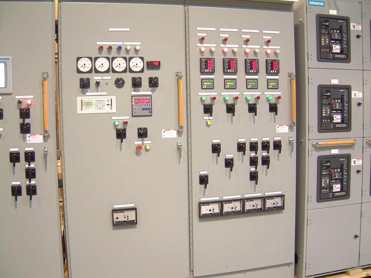
Power distribution, with purpose.
A facility’s switchgear should reflect how its loads behave, how much interruption it can tolerate and how maintenance fits into daily operations. A data center, water plant, hospital and manufacturing line may all need dependable distribution, but their outage risks, operating schedules and equipment interfaces differ. Matching the assembly to those conditions starts with the facility’s one-line diagram and a clear account of how the site is used.
Start with the consequence of an interruption
Classify loads by what happens if power is lost, not merely by their size. A process line may lose product or require a controlled restart; a pump station may lose flow; and a critical IT load may depend on a coordinated transfer to alternate power. Identify which loads must remain supplied, which can be shed, and which can tolerate a planned outage. This helps define bus arrangement, feeder grouping and provisions for future connections without treating every circuit as equally critical.
Also document the operating sequence during utility failure, generator operation and restoration. Switchgear interfaces with protective relays, transfer equipment, generators, UPS systems and building controls, but those devices do not automatically form a coordinated system. The purchaser’s design team should establish control ownership, interlocks, status signals and operating responsibilities. A proposed arrangement should be reviewed against the one-line diagram and the facility’s actual sequence before equipment is released.
Data centers and other continuous-service sites
For data centers, laboratories and similar facilities, the key question is how distribution paths support the required operating model. Confirm whether equipment serves an A-side, B-side or shared path, and identify any tie breakers, maintenance bypass arrangements or downstream transfer devices. A tie can improve flexibility, but its normal position and permitted operating states must be explicit; an unclear tie strategy can create unintended parallel sources or complicate fault isolation.
Review metering, alarms and communications as part of the specification rather than after the lineup is designed. Operators may need breaker status, trip indication, source availability and metered values at a supervisory system, with defined protocols and point lists. Consider where technicians will stand to read indicators, operate devices and connect test equipment. The owner’s maintenance policy, arc-flash risk assessment and applicable electrical safety procedures should inform access and work planning; no switchgear feature replaces safe isolation practices.


Process plants and manufacturing facilities
Industrial loads often combine steady demand with large motor starts, variable-frequency drives, welders, furnaces or cyclical production equipment. Supply the motor list, starting method, drive details and expected operating sequence so engineers can assess loading, voltage drop, harmonics and protective-device coordination. A nameplate total alone can misrepresent demand, while a future production expansion may change feeder sizes or available fault current. Explain which loads can restart together and which must be sequenced.
The environment matters as much as the electrical schedule. Describe dust, moisture, corrosive exposure, ambient temperature, vibration and available indoor space, and identify cable entry direction and working clearances. For a production facility, maintainability may depend on isolating one section while other processes continue; that goal must be reconciled with bus configuration, protection and the owner’s operating procedures. Any change to an existing lineup also requires confirmation of interface dimensions, bus details and system conditions rather than assumptions based on appearance.
Healthcare, water and public infrastructure
Hospitals and other essential-service buildings have loads with different restoration priorities, from life-safety and essential systems to comfort and noncritical functions. The electrical design team should identify the governing code requirements, source arrangement and transfer sequence for the specific facility. Switchboard sections and feeder design need to support that approved design, while maintaining clear separation and identification where required. Do not infer an equipment listing or code approval from a general product description; confirm the applicable requirements for the actual order.
Water and wastewater facilities add outdoor exposure, remote controls and long-running motor loads to the evaluation. Clarify whether the equipment is indoors or in an enclosure, how control and telemetry signals connect, and what operating conditions apply during utility interruptions. Municipal and institutional owners may also need planned outage windows, spare-circuit strategy and documentation suitable for future maintenance. These details help balance resilience against complexity: additional sections, ties or controls can improve flexibility but also add interfaces that must be tested, documented and maintained.
Match construction and ratings to the application
Specify the system’s nominal voltage, phase, frequency, grounding method and service configuration, then distinguish those system values from the equipment’s maximum voltage rating. Provide available fault current at the proposed equipment location, the required short-circuit rating and the protective-device information used for coordination. Ratings cannot be selected from facility type alone. They depend on the source, transformer data, upstream protection, conductor impedance and the intended operating configuration, including generator or tie operation where applicable.
For low-voltage distribution, a UL 891 switchboard may be appropriate when the design and specific assembly meet the applicable requirements; UL 891 is not a general listing for medium-voltage or high-voltage switchgear. Medium-voltage class equipment requires its own application-specific evaluation. Confirm standards, component availability, US-origin requirements and any required documentation for each order. Custom construction using American components and a shorter lead time can be goals, but the achievable design, sourcing and schedule must be confirmed for the requested configuration.
Prepare a quote package around the real facility
A useful quote request includes the latest one-line diagram, load and feeder schedules, source and transformer data, available fault-current study, protective-device preferences and required control or metering interfaces. Add enclosure location and environmental conditions, cable entry and termination needs, dimensions or access constraints, preferred make and model of components where applicable, and any project specifications. Identify the facility type, critical loads, redundancy intent and planned expansion so the proposed assembly can be evaluated against the operating need rather than a generic template.
For Dallas–Fort Worth facilities and projects shipped elsewhere in the United States, provide delivery destination, receiving constraints and the date equipment is needed for coordination; these details do not establish a local manufacturing or installation service. The manufacturer builds and supplies switchgear, and can review the submitted requirements for a custom configuration. Before an order is finalized, the purchaser and engineering team should resolve drawings, ratings, interfaces, standards and component substitutions. Final availability and US-origin status are order-specific, as is any schedule.
Specifications & planning
Review the details that matter for your application. Final specifications and availability should be confirmed for your project.
| Evaluation factor | Information to establish |
|---|---|
| Interruption risk | Critical loads, acceptable outage and restoration sequence |
| Load profile | Demand, motor starts, drives and simultaneous operation |
| System interface | Sources, ties, transfer equipment, controls and metering |
| Site conditions | Environment, access, cable entry and maintenance constraints |