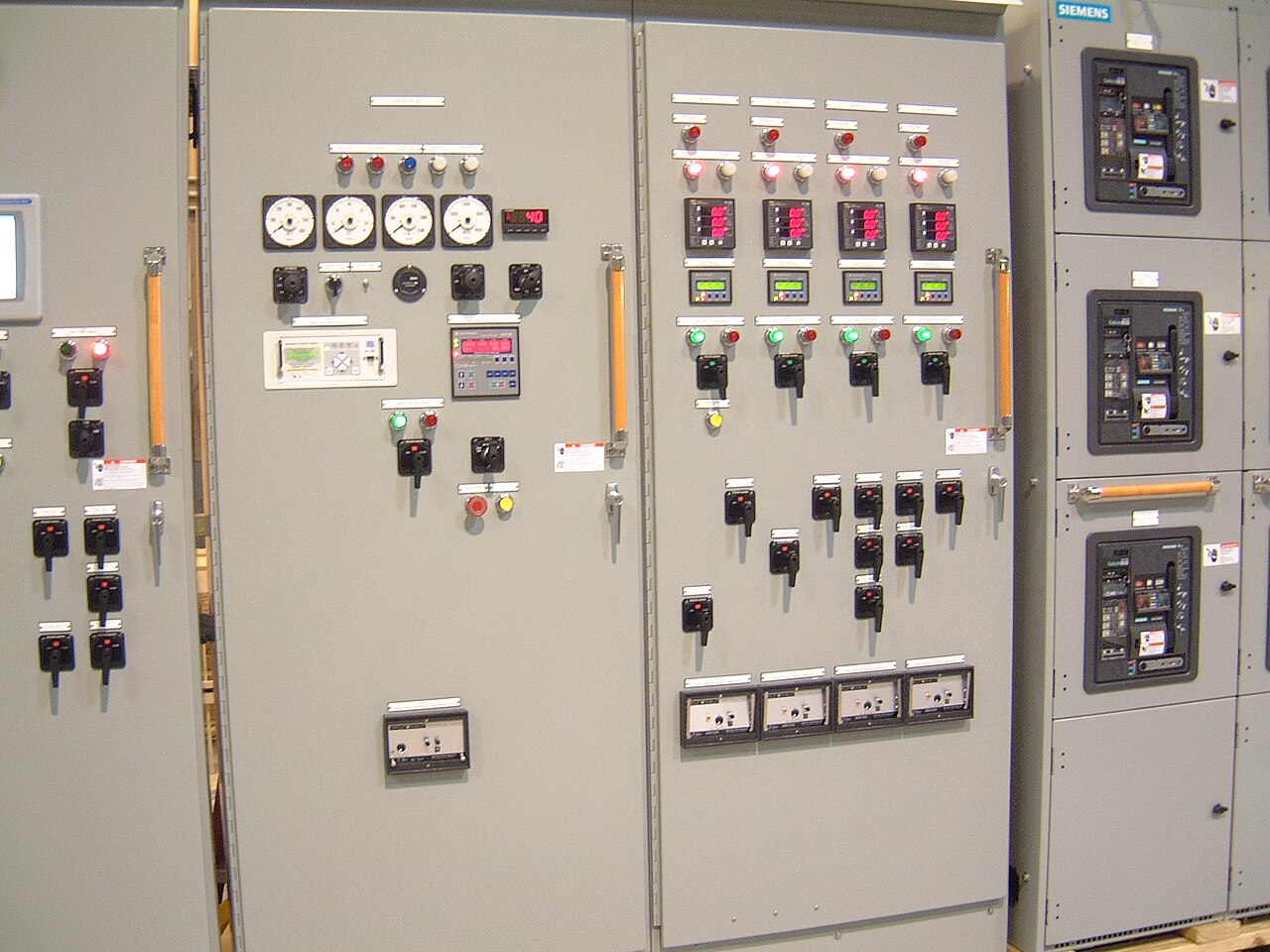
Power distribution, with purpose.
Projects across Dallas–Fort Worth and North Texas can be supplied without assuming the manufacturer has a factory in the region. The practical starting point is a clearly defined electrical scope: what the equipment must control, how it connects to the site, and what constraints govern delivery and installation. New custom-built switchgear can be developed around project requirements, with American components and a shorter lead time as a goal; the actual design, availability, schedule, and applicable standards must be confirmed for each order.
Define the project boundary before selecting equipment
A North Texas project may involve a new facility, an expansion, or replacement equipment, but the switchgear scope should be described in terms of electrical function rather than geography alone. Identify the service entrance, distribution points, major loads, and equipment supplied by others. State whether the requirement is for a low-voltage switchboard, medium-voltage gear, or a coordinated combination. That distinction affects the design, interfaces, applicable standards, and information needed for a reliable quote.
For a Dallas–Fort Worth site, confirm the serving utility’s requirements and the project engineer’s basis of design rather than relying on a generic regional assumption. Utility ownership boundaries, metering provisions, available fault current, and service voltage can differ by project. Provide the one-line diagram and any utility or consultant criteria available. If documents are preliminary, label open items so they can be treated as assumptions—not silently converted into equipment commitments.
Resolve ratings and protection from project data
A nominal system voltage is not, by itself, a complete equipment rating. The quote package should identify the nominal voltage, frequency, grounding arrangement, and the required equipment maximum voltage where applicable. For medium-voltage applications, state the intended class—commonly 5 kV, 15 kV, 27 kV, or 35 kV in this context—and have the specific design reviewed. Do not treat those classes as low-voltage switchboard ratings or assume UL 891 applies to them.
Short-circuit duty and protective-device coordination are equally important. Supply the available fault-current study or its approved design basis, required withstand or interrupting values, protective-device preferences, and any coordination constraints. These values depend on the system and configuration; they cannot be inferred just from the city or nominal voltage. Ratings, component availability, standards, and any required U.S.-origin provisions must be confirmed for the particular order.


Coordinate connections, controls, and neighboring equipment
A switchgear lineup is only useful if its electrical and physical interfaces match the rest of the project. Identify incoming and outgoing cable or bus connections, feeder quantities, conductor entry direction, termination requirements, and the equipment on each side of the lineup. If transformers, generators, utility gear, transfer equipment, or remote distribution boards are involved, share their relevant drawings and ratings. Differences in connection space or interface assumptions can create late design changes even when the one-line diagram appears complete.
Control and communication requirements deserve the same early attention. Specify control power, metering functions, protective relays where applicable, interlocks, remote status points, and required communication protocols. Clarify which party supplies wiring, network devices, and field terminations. For a custom build, these choices influence component selection and internal arrangement; a requested feature should not be assumed available or compatible until engineering review confirms the specific configuration.
Plan delivery around the actual North Texas site
Serving Dallas–Fort Worth does not mean a local factory or a particular shipping route should be assumed. Delivery planning should use the project’s real destination, receiving conditions, and installation sequence. Tell the manufacturer whether the site has restricted truck access, limited unloading equipment, scheduled receiving windows, or a constrained laydown area. Confirm the delivery configuration, shipment divisions, and handling responsibilities before the equipment is released.
Access and building conditions can matter as much as the final set location. Provide the room dimensions, doorway and corridor constraints, floor or loading limitations, and any required lifting or rigging clearances. Identify whether the lineup must pass through a particular opening or be positioned before adjacent construction is complete. These details help evaluate feasible dimensions and shipping sections early, while avoiding unsupported promises about delivery dates or site services.
Make schedule expectations specific and verifiable
For a project schedule, distinguish the desired equipment-on-site date from the dates for approved drawings, submittal review, manufacturing release, shipment, and installation readiness. A shorter lead time may be a goal, but it is not a guarantee. The achievable schedule depends on engineering completeness, approval cycles, selected components, factory workload, and any project-specific testing or documentation requirements. Ask for the current schedule basis and identify decisions that could affect it.
Submittal timing is a particular risk when the site schedule is aggressive. Submit the latest one-line diagram, load and feeder information, physical constraints, and control requirements together where possible. Mark revisions clearly and identify who has authority to approve deviations. Changes after design approval can affect both cost and timing, so the purchaser should establish a process for resolving engineering comments and confirming the final scope before the build proceeds.
Prepare a quote package that supports an accurate review
A useful request for quote states the project location in North Texas, equipment type and scope, nominal system voltage, required equipment ratings, one-line diagram, feeder schedule, and available fault-current information. Include dimensions or room drawings, connection orientation, environmental conditions, control and metering requirements, and the requested standards or specifications. Note whether the project requires UL 891 low-voltage switchboards, where applicable; do not apply that standard as a general requirement for medium-voltage or high-voltage gear.
Also provide the preferred delivery window, submittal deadline, shipment destination constraints, and any U.S.-origin or component restrictions. Identify what remains unknown and who will supply the missing design inputs. Custom builds can be tailored to a project, but an incomplete package may require clarifications before scope, component availability, ratings, compliance, or schedule can be confirmed. A documented quote basis gives the purchaser and manufacturer a common reference for evaluating changes.
Specifications & planning
Review the details that matter for your application. Final specifications and availability should be confirmed for your project.
| Evaluation factor | Information to establish |
|---|---|
| Electrical basis | Nominal voltage, grounding, fault-current data, and required equipment ratings |
| Scope and interfaces | One-line diagram, feeder schedule, connection details, and adjacent equipment |
| Site delivery | Destination, access limits, unloading arrangements, and receiving window |
| Schedule and compliance | Key dates, approval cycle, applicable standards, and any origin requirements |