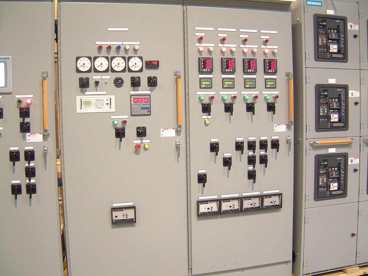
Power distribution, with purpose.
In a hypothetical manufacturing facility, switchgear is not simply the point where incoming power is divided among loads. Its configuration affects how motors start, how faults are isolated, which production areas remain available during an outage, and whether a later production line can be added without reworking the entire distribution system. Good selection begins with the process and its operating priorities, then turns those needs into verified electrical, physical, and control requirements.
Start with the production process and continuity targets
Map the electrical path from the utility or onsite source to the plant’s major loads. A manufacturing site may have process lines, pumps, compressors, dust collection, HVAC, material handling, and office loads with different consequences when power is lost. Identify which loads must stop immediately, which can coast or complete a controlled shutdown, and which should remain energized. This distinction helps determine whether distribution should be grouped by process, production area, or operational priority rather than arranged only for convenience.
Consider what an interruption means for the process, not only the number of minutes without power. A stopped conveyor may be restartable, while a batch process could require controlled recovery, inspection, or disposal of material. Define acceptable outage and restoration expectations with operations and facility engineering. These are planning inputs, not switchgear performance guarantees; source redundancy, transfer equipment, protective coordination, and the facility’s operating procedures all affect continuity.
Translate motor data into equipment requirements
Motor nameplate information is essential because motor loads can impose substantial starting current and affect voltage conditions on shared distribution. For each significant motor, provide horsepower or kilowatts, voltage, full-load current, starting method, duty, and any variable-frequency drive or soft starter. Also identify simultaneous starts and the loads that operate together. A large motor starting across the line can influence upstream voltage and protective-device selection differently from a drive-controlled motor, so a simple total connected-load figure is not enough.
The switchgear specification should distinguish the system’s nominal voltage from the equipment’s maximum voltage rating and state the available fault current at the connection point. Include the required continuous current and short-circuit withstand or interrupting criteria as applicable to the assembly and its protective devices. Do not infer these values from a general voltage description. They require utility or system data and engineering review, with final ratings and component availability confirmed for the specific order.


Coordinate protection, controls, and operating interfaces
Protection should reflect the plant’s distribution arrangement and the need to isolate faults selectively where the design permits. The engineer needs source and transformer information, conductor and feeder data, motor contributions, and the applicable fault-current study assumptions to evaluate device settings and coordination. A setting that clears a fault quickly may reduce equipment exposure, but settings also must be coordinated with upstream and downstream devices. Selectivity cannot be promised without reviewing the actual system and protective-device characteristics.
Define the signals and operator interfaces before equipment is ordered. A facility may need breaker status, trip indication, metering, alarms, remote monitoring, or interlocks with process controls. Specify communication protocols, point lists, control power, and any required interface boundaries, including who supplies field wiring and who verifies signals during commissioning. Interlocks and remote functions should be documented so operators understand permitted states; equipment design does not replace site procedures or qualified personnel.
Fit the assembly to the plant room and delivery route
Manufacturing spaces often have constraints that are easy to miss on a one-line diagram. Provide room dimensions, ceiling height, doorway and corridor clearances, floor conditions, ventilation or environmental concerns, and the intended working and access clearances. Check the route from receiving to the final room, including turns, thresholds, lifts, and restrictions on moving large sections. A lineup that fits the electrical room may still be difficult to deliver or position if the route and installation sequence are not considered early.
Also identify cable entry direction, conduit or busway connections, incoming source location, and the space needed for future sections or feeder additions. In a production plant, locating equipment too close to process hazards, washdown areas, vibration, heat, or airborne contaminants can create operational and maintenance concerns. Share relevant environmental conditions and layout drawings for review. Custom configurations may help address a project’s constraints, but dimensions, construction details, and interfaces must be confirmed for the specific design.
Plan expansion and maintenance before release
Process expansion is easier to evaluate when the owner identifies likely additions before finalizing the lineup. Describe planned production lines, anticipated motor loads, reserved feeder ways, and whether future work may require an additional source or a different distribution arrangement. Spare physical space alone does not establish electrical capacity: the source, bus, protective devices, conductors, fault duty, and operating strategy all need review. Deliberate allowances can preserve options, while oversized or unused provisions may increase cost and occupy valuable plant space.
The owner’s maintenance program should address the equipment documentation and responsibilities needed after delivery. Clarify who maintains settings and records, tracks changes to connected loads, arranges inspections, and coordinates qualified service under applicable procedures. Keep approved drawings, device data, test records, and operating instructions accessible, and reassess protection when the plant changes. Before publication or purchase, validate manufacturer capabilities, applicable standards, component availability, and any U.S.-origin requirements against the project specification; UL 891 applies to low-voltage switchboards where applicable, not medium-voltage gear generally.
Prepare complete information for a new-equipment quote
A useful quote request includes the one-line diagram, system nominal voltage, available fault current or study basis, source and transformer details, load schedule, major motor data, and required protective-device functions. Add the preferred lineup arrangement, cable entry and connection requirements, control and communications points, applicable project specifications, and requested documentation. For a manufacturing facility in Dallas–Fort Worth or elsewhere, also provide the electrical-room and delivery-route drawings, environmental conditions, and the schedule constraints that matter to the project.
The manufacturer builds and supplies new equipment; buying inquiries are requests for a new custom assembly, not offers to purchase used gear. Identify the required equipment type and application, desired ship-to location, target timing, and any required standards or component-origin clauses. A shorter lead time may be a project goal, but timing depends on design review, component availability, and order-specific requirements and should be confirmed rather than assumed. Complete source data helps the manufacturer and project engineer resolve scope, ratings, interfaces, and exceptions before release.
Specifications & planning
Review the details that matter for your application. Final specifications and availability should be confirmed for your project.
| Evaluation factor | Information to define |
|---|---|
| Motor demand | Nameplate data, starting method, and operating sequence |
| Electrical duty | Nominal system voltage, fault-current basis, and protection criteria |
| Continuity priorities | Loads requiring controlled shutdown or prioritized restoration |
| Physical fit | Room layout, access clearances, cable entry, and delivery route |