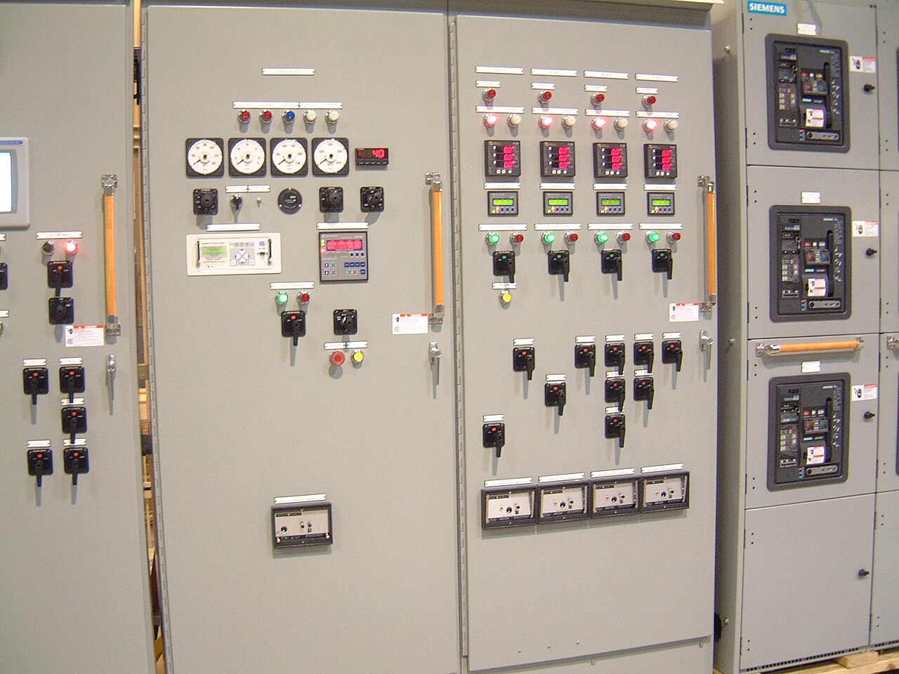
Power distribution, with purpose.
Oil and gas process power distribution must deliver power to motors and supporting loads while limiting the reach of a fault or planned outage. The right switchgear arrangement depends on the process sequence, motor characteristics, available fault current, and the consequences of losing each load—not just the facility’s total demand.
Start with the process, then size the motor feeders
Build the distribution plan from the process load list. Identify each motor’s driven equipment, horsepower or kilowatt rating, voltage, full-load current, starting method, duty cycle, and operating role. A large pump or compressor may dominate feeder selection, but smaller motors can be equally important if they support cooling, lubrication, sealing, ventilation, or instrument systems. Record which loads run continuously, intermittently, or only during startup and shutdown.
Motor starting can affect both feeder design and upstream voltage stability. Across-the-line starting, reduced-voltage methods, and variable-frequency drives present different current profiles, protection needs, and interfaces. Specify the starter or drive arrangement, bypass requirements, control power, and any manufacturer-specific coordination requirements. Confirm that the selected equipment’s bus and feeder ratings suit the actual load and that the available short-circuit rating is adequate for the calculated fault current.
Separate loads by their process and outage consequences
Load segregation helps operators contain an outage without unnecessarily interrupting unrelated process areas. The one-line diagram should show which motors and auxiliaries share a bus, switchboard section, transformer, or upstream source. Grouping by process unit may simplify operations, while separating essential auxiliaries from large process motors can reduce the chance that a fault or maintenance outage disables both the main load and the support systems it needs.
Segregation is a tradeoff, not an automatic benefit. More sections, ties, and alternate feeds can improve operating flexibility, but they add switching decisions, protection coordination work, and potential paths for a fault to propagate. Define normal and contingency operating configurations, including whether a tie is normally open or closed and what loads may transfer. The owner’s operating philosophy and protection engineer should establish those boundaries before the equipment arrangement is finalized.


Design for selective fault isolation
A useful fault-isolation strategy aims to trip the smallest practical portion of the distribution system while protecting conductors and equipment. That requires a coordination study using the actual source data, transformer impedances, conductor details, motor contribution assumptions, and protective-device characteristics. The study should address relevant operating modes, since utility supply, onsite generation, or a bus-tie configuration can change available fault current and coordination behavior.
Specify the protection and control functions required at each level, rather than relying on a general request for coordinated protection. Consider feeder overcurrent protection, ground-fault protection where applicable, breaker trip and close controls, status indication, metering, interlocks, and interfaces to plant control or supervisory systems. Confirm how trip signals and alarms will be exchanged, who supplies interface wiring or communications equipment, and what testing and documentation are required. Final settings and protection decisions belong to the responsible electrical engineer and owner.
Illustrative scenario: preserve support loads during a motor fault
As a hypothetical example, consider a process area with a large pump motor and separate motors for lubrication and cooling. If all three loads are placed on one section without regard to their roles, a fault on the pump feeder could have broader consequences than intended. A design review could evaluate feeder-level isolation, the placement of support loads, and whether dividing the loads across sections would reduce risk without creating an undesirable operating dependency.
That review would need to test more than the normal lineup. Engineers would examine fault current, device selectivity, motor starting interactions, alternate-source availability, and what happens if a section or tie is out of service. The arrangement should not assume an automatic transfer or continued operation unless the controls, protection, and operating procedures support it. This scenario illustrates a decision process only; it does not describe a completed project or guarantee continuity.
Bring stakeholders and interface details into the specification
A quote-ready package should include the latest one-line diagram, load schedule, system nominal voltages, source and transformer data, available fault current, and required bus and feeder ratings. Provide motor data and starting methods, the intended operating configurations, protection-study requirements, environmental conditions, and any hazardous-location or installation constraints that affect the equipment interface. State whether the scope includes control wiring, metering, communications provisions, spare feeders, and factory or site testing.
Operations, process engineering, electrical engineering, protection and controls teams, procurement, and the authority having jurisdiction may all shape the final requirements. Clarify who approves the one-line, settings, interlocks, and equipment submittals, and who is responsible for field connections and commissioning. A manufacturer can build to an agreed specification; it should not be assumed to select process-critical loads, approve protection settings, or establish code acceptance in place of the owner’s engineer or reviewing authority.
Balance configuration, delivery goals, and approval boundaries
Selection tradeoffs include a simple radial arrangement versus sectionalized buses, fixed versus drawout devices where applicable, and integrated motor-control functions versus separate equipment. Consider maintainability, footprint, operator familiarity, future load growth, and the consequences of a failed component alongside initial equipment cost. Custom-built new equipment can be configured around project requirements, with American components and shorter lead time as goals; actual component availability, schedule, and origin requirements must be confirmed for the specific order.
For facilities in Dallas–Fort Worth or elsewhere in the United States, shipping and site access planning should account for equipment dimensions, handling limits, receiving arrangements, and the construction sequence. Low-voltage switchboard assemblies may be designed to applicable UL 891 requirements when specified and confirmed; that standard does not apply as a general listing for medium-voltage switchgear. Confirm nominal system voltage separately from equipment maximum rating, along with interrupting and withstand ratings, applicable standards, and any project or procurement requirements. Final acceptance rests with the owner’s engineer and applicable authorities.
Specifications & planning
Review the details that matter for your application. Final specifications and availability should be confirmed for your project.
| Evaluation factor | Information to confirm |
|---|---|
| Motor feeders | Motor ratings, starting method, duty, and support-load dependencies |
| Load segregation | Bus sections, normal lineup, tie position, and contingency configuration |
| Fault isolation | Available fault current, protection study basis, and required interfaces |
| Approvals and scope | Submittal reviewers, testing responsibilities, standards, and delivery constraints |