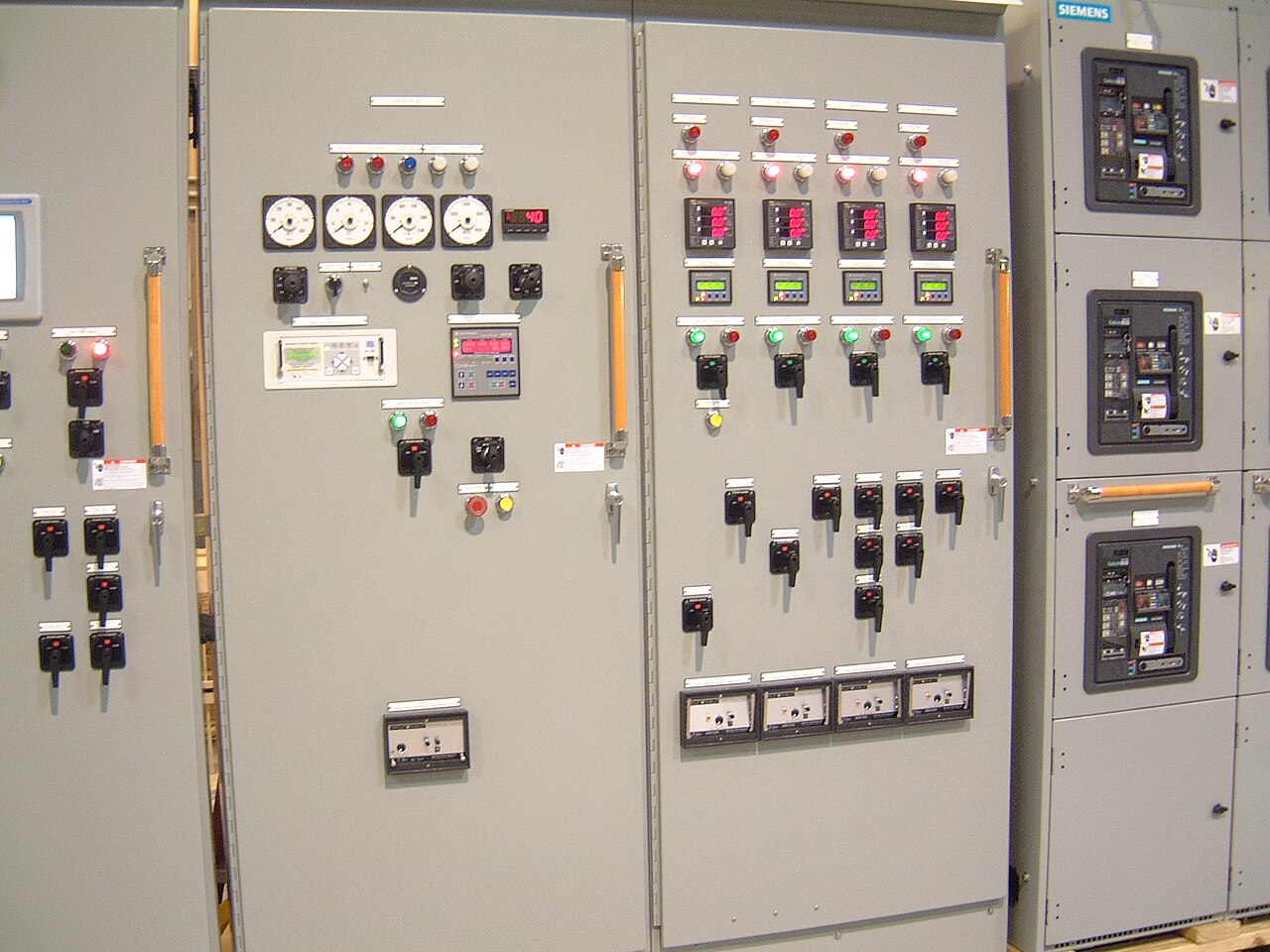
Power distribution, with purpose.
Busbar bending and clearance planning turn electrical and mechanical requirements into copper or aluminum conductors that fit, remain supported, and can be assembled and inspected. A bend that looks workable on a layout may conflict with an enclosure, block tool access, or reduce phase spacing after fabrication. For new switchgear, these decisions belong in coordinated design review—not as assumptions left for the shop floor or field crew.
Start with geometry and electrical duty
A useful design starts with the busbar material, thickness and width, conductor count, system configuration, and intended route through the assembly. Drawings should identify connection points, terminal faces, transition pieces, and fixed obstructions. The equipment’s nominal system voltage is not, by itself, enough to set clearances: the applicable equipment rating, insulation system, construction, and governing project requirements also matter. Short-circuit duty and heating requirements affect conductor dimensions, bracing, and support design, so a bend cannot be reviewed in isolation.
Bend geometry includes the direction and angle of each bend, the inside radius, straight length available before and after the bend, and the position of the finished conductor relative to its mounting plane. The selected radius must suit the material and fabrication method while avoiding unacceptable distortion or damage. A tighter bend may save space but can complicate tooling, stress the conductor, or reduce access at a joint. Final dimensions and allowable tolerances should be established for the specific order rather than inferred from a generic shop rule.
Coordinate clearances across the complete assembly
Phase spacing must be checked in the actual assembled configuration, including bends, overlaps, insulating barriers, hardware, and nearby grounded metal. Measure from the relevant conductive surfaces, not only from nominal conductor centerlines. The review should account for the equipment’s electrical design and applicable standards, with allowances for manufacturing tolerances and any movement or deflection considered in the design. No single spacing value applies to every voltage class, construction, or application.
Clearance planning also includes the space needed to install and inspect joints, fit barriers, route cables, and remove or replace parts where the design requires it. A bus run that clears in a two-dimensional view may approach a side panel, door, or neighboring phase when viewed in three dimensions. Coordination with the enclosure, breaker or switch components, instrument connections, and incoming or outgoing terminals is essential. Changes at one interface can shift the conductor route and require a fresh clearance review.


Place supports for mechanical performance and access
Support locations influence how busbars carry their own weight and respond to electrical forces during a fault. The engineering review should consider conductor span, orientation, joint locations, support material and arrangement, and the assembly’s specified short-circuit duty. A long unsupported span may be difficult to control; adding a support without checking phase spacing or insulation can introduce a new interference. Support spacing and bracing must therefore follow the design for the specific assembly, not an assumed universal interval.
Supports also shape the practical work sequence. Their position can determine whether a conductor can be inserted, whether joint hardware can be reached with the intended tools, and whether barriers can be installed without forcing or damage. Manufacturer design rules define the approved geometry, interfaces, tolerances, and inspection points for the build. Field practices address handling and installation conditions at the site; they do not authorize unreviewed changes to bus shape, spacing, support points, or electrical design.
Use coordinated inputs and review tradeoffs early
For a quote and engineering review, purchasers should provide the one-line diagram, system voltage and frequency, required continuous current and short-circuit duty, applicable specifications, and the desired equipment configuration. Include available enclosure or room dimensions, cable entry direction, connection dimensions, terminal orientation, and known adjacent equipment interfaces. Existing drawings, approved component selections, material preferences, and project-specific U.S.-origin requirements are useful where applicable. Missing information should be identified as an open item rather than filled with an assumed rating or dimension.
The design tradeoff is often between a compact route and a bus arrangement that is easier to fabricate, inspect, connect, and maintain. Larger bend radii or more generous access can require additional enclosure space; tighter packaging may affect tooling access, barriers, or assembly sequence. Custom builds using American components and a shorter lead time as a goal may be considered, but component availability and schedule depend on the confirmed design and order. Ratings, short-circuit capability, standards, material origin, and any required compliance evidence must be confirmed for the specific assembly.
Define drawing outputs and scope boundaries
A coordinated drawing package can show bus routes and bend callouts, conductor dimensions and material, support and joint locations, phase-to-phase and phase-to-ground clearance review points, and interfaces to enclosure walls and connected components. Depending on project scope, it may also identify hardware, barriers, tolerances, and the revision status used for fabrication. These records make design intent reviewable and help prevent a field fit-up issue from being mistaken for permission to alter the electrical arrangement.
Before release, the purchaser and manufacturer should agree on which party supplies interface dimensions, reviews drawings, resolves conflicts, and approves changes. Site measurements or field modifications should be handled by qualified personnel under the project’s approved procedures, with revised drawings and engineering review when they affect the assembly design. This page describes planning considerations, not a claim that every bend geometry, material, or configuration is available. For Dallas–Fort Worth projects and shipments elsewhere in the United States, the same project-specific confirmation is needed before fabrication.
Specifications & planning
Review the details that matter for your application. Final specifications and availability should be confirmed for your project.
| Evaluation factor | What to confirm |
|---|---|
| Bend definition | Material, thickness, width, radius, angle, and dimensional tolerances |
| Clearance basis | Equipment rating, applicable requirements, barriers, and grounded surfaces |
| Mechanical design | Short-circuit duty, support locations, spans, and joint arrangement |
| Assembly interfaces | Enclosure envelope, tool access, terminals, and installation sequence |