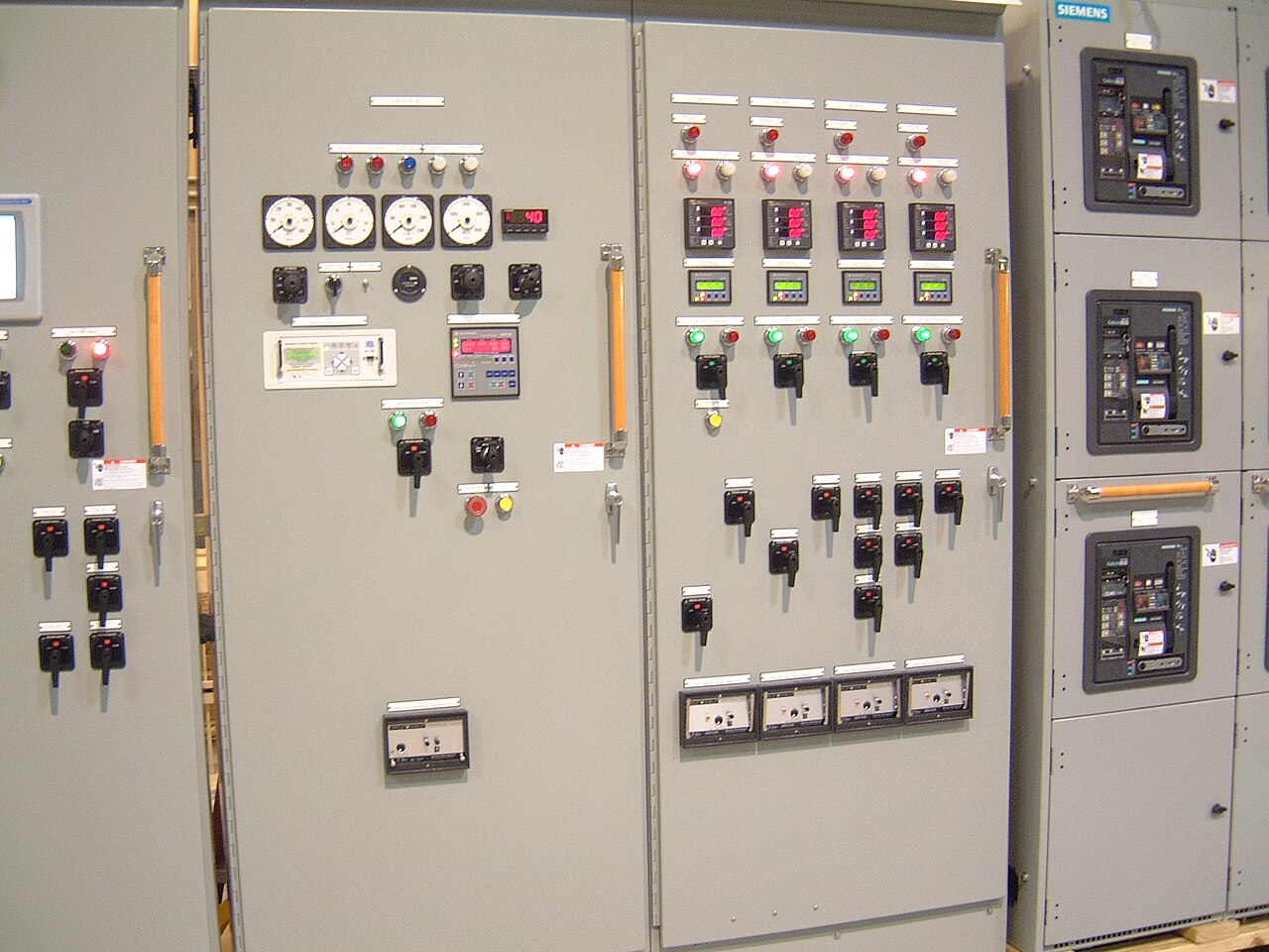
Power distribution, with purpose.
Control wiring and terminal classes determine how an MCC communicates with its motors, process controls, and building systems—and who is responsible for completing each connection. The right arrangement depends on the applicable standard, the specific assembly, and the project’s division of work, so confirm both before fixing the specification.
Start with the applicable standard and assembly
“Control wiring” can mean conductors within a motor starter unit, wiring between units, connections to a common terminal block, or interfaces extending to an external PLC or control panel. These are different boundaries. A specification should identify which conductors and devices are included in the MCC, where factory wiring ends, and which connections are made at the jobsite. A terminal class or designation may describe a termination arrangement under a particular standard; it should not be treated as a universal shorthand for every wire, terminal, or scope obligation.
Before selecting a class, identify the governing standard and edition, the MCC construction and intended use, and any project or owner requirements that modify the baseline. Applicability depends on the actual product and configuration; a standard reference alone does not establish that a particular assembly complies. Confirm the proposed terminal arrangement, documentation, and available components for the specific order. Applicable ratings and standards must be reviewed for that assembly rather than inferred from a generic product description.
Define the control-wiring architecture
The design may use hardwired control circuits, a networked control interface, or a combination. Hardwired circuits can make discrete commands and status points straightforward to trace, but they require enough conductors, terminals, wireway capacity, and carefully coordinated point-to-point drawings. Network communication can reduce some field conductors, yet depends on compatible devices, an agreed protocol, network architecture, and clear responsibility for configuration and testing. A network does not automatically eliminate hardwired safety, permissive, or status signals required by the design.
Specify the expected control voltage and source, circuit protection and isolation approach, conductor identification, terminal labeling, and whether spare terminals or spare conductors are needed. Also clarify how control power behaves when a unit is withdrawn or isolated, where common and shield terminations belong, and whether interlocks or remote signals cross MCC sections. These details affect wiring space, separation, troubleshooting, and the information an assembler can provide. Do not assume that a control feature or communication option is available until it is confirmed for the proposed lineup.


Make field termination responsibility explicit
A useful scope boundary names the last factory-terminated point and the first field-terminated point. For example, a hypothetical project might require factory wiring from a starter’s control device to a terminal block inside the MCC, while the installing contractor lands customer-supplied control cables on designated terminals. That arrangement is only an example, not a claim about a completed project or universally available construction. The purchaser and manufacturer should agree whether the quoted work includes internal wiring, terminal blocks, inter-unit connections, external interface terminals, wire markers, and wiring diagrams.
Field responsibility also includes supplying and routing the external cable, verifying conductor and lug suitability, making terminations, and completing project-required checks; the actual division must be stated in the contract documents. Coordinate who supplies control devices and cables, who provides the final point schedule, and who approves changes after drawings are released. Ambiguous boundaries can leave missing terminals, duplicate wiring, or controls that cannot be commissioned as intended. Installation, field wiring, and commissioning should not be assumed to be included in an equipment quotation unless explicitly confirmed.
Use a representative design scenario to test choices
Consider a hypothetical water-process MCC with across-the-line starters, remote run and fault indications, and a plant PLC. If operators need simple discrete points and the PLC contractor owns the external cable, a terminal-block interface may provide a legible handoff. The design team would still need to settle the point list, signal type, control-power source, terminal numbering, and which signals are required for each starter. A drawn interface schedule can expose gaps before the lineup wiring is finalized.
If the same project instead uses networked motor-control devices, the team must define the protocol, addressing and configuration responsibilities, communication path, and what happens when communication is unavailable. Retaining selected hardwired signals may be appropriate where the control narrative, risk assessment, or owner standard calls for them. Neither approach is inherently best: the tradeoff is between wiring and terminal complexity, maintainability, integration effort, and the consequences of a lost signal. Engineering and owner approval should resolve those choices before they become procurement assumptions.
Coordinate interfaces and drawing approvals
MCC control connections intersect with the PLC or DCS integrator, electrical contractor, motor and driven equipment suppliers, and sometimes fire-alarm or building-control systems. Establish who owns the control narrative, I/O list, external schematics, network design, and cable schedule. Confirm signal naming and terminal numbering across documents, as well as the treatment of shield drains, grounding, isolation, and spare points. A consistent interface schedule is especially valuable when equipment ships to a Dallas–Fort Worth project from a manufacturer serving customers nationwide, because the documents must make the field handoff clear without relying on informal assumptions.
Review approval drawings for the exact terminal locations, unit boundaries, internal and external wiring demarcation, control-device details, and referenced drawing revisions. A purchaser should identify the engineer or owner representative authorized to approve them and the process for recording changes. Approval of drawings does not by itself settle deviations from the purchase specification, nor does it verify field cable design or contractor workmanship. Confirm what documents and revisions are included in the order, and request clarification where a standard, specification, or interface requirement conflicts with another.
Prepare quote inputs and verify availability
For a useful quote, provide the one-line diagram and MCC schedule, system nominal voltage and frequency, unit types, control schematics or narrative, I/O list, required communications, and the governing standard and edition. Include the specified terminal class or arrangement, if known, plus conductor details, terminal quantities, spare-point expectations, labeling rules, cable-entry constraints, and environmental or enclosure requirements. State the field-termination boundary and identify owner-specific documents or deviations. Ratings, short-circuit requirements, component availability, and any U.S.-origin requirements must be checked against the specific order rather than assumed from a general description.
The manufacturer builds and supplies new equipment and can evaluate custom arrangements using American components where suitable. Shorter lead time is a goal, not a guarantee; component selection, approved drawings, and project requirements affect schedule and feasibility. Ask for confirmation that the requested terminal arrangement, wiring scope, and documentation are available for the proposed assembly before treating them as committed. A clear scope review helps the purchaser compare quotations on equivalent boundaries and prevents a low apparent price from hiding field wiring or integration work that another bid includes.
Specifications & planning
Review the details that matter for your application. Final specifications and availability should be confirmed for your project.
| Evaluation factor | Decision to document |
|---|---|
| Wiring architecture | Hardwired points, network interface, or a defined combination |
| Termination boundary | Factory-terminated endpoint and field-terminated endpoint |
| Terminal arrangement | Applicable standard, class or designation, and assembly-specific confirmation |
| Quote inputs | Schematics, I/O list, device schedule, cable details, and owner requirements |