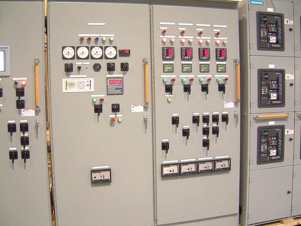
Power distribution, with purpose.
A variable-frequency drive (VFD) changes more than a motor’s speed: it affects the heat load, electrical characteristics, protection scheme, physical layout, and control interfaces of the motor control center (MCC). A useful specification starts with the motor and operating duty, then checks how the drive section will fit and function alongside the rest of the lineup. These decisions help identify design constraints early, before a new MCC assembly is quoted or approved.
Start with the motor and operating duty
The drive must be matched to the motor’s electrical and mechanical requirements, not selected from horsepower alone. For each driven load, provide motor nameplate data, system voltage and frequency, full-load current, motor type, and any known service-factor or insulation details. Describe the operating profile as well: expected speed range, starts and stops per hour, acceleration and deceleration needs, continuous or intermittent duty, and whether the load is constant-torque or variable-torque. Pumps, fans, conveyors, and compressors can impose different demands even when their motor ratings appear similar.
Also identify the driven equipment’s operating limits and the process behavior expected during a fault or shutdown. A fan that can coast down may present different stopping requirements from a conveyor that must stop predictably to protect material or machinery. Confirm whether the VFD is expected to provide local control, receive speed references from a plant control system, report status remotely, or support a defined control protocol. These inputs let the design team assess the drive section and interfaces without assuming the application or choosing controls that the purchaser has not requested.
Account for heat and lineup space
A VFD produces heat that must be managed within the MCC enclosure and the room where the lineup will operate. The relevant review includes drive losses, other heat-producing components, enclosure construction, ambient temperature, elevation when applicable, and the planned ventilation or cooling approach. Closely packed drive sections can affect neighboring units as well as the drive itself. If the MCC will operate in a warm, dusty, damp, or otherwise demanding environment, provide those conditions rather than assuming a standard indoor setting.
Physical integration deserves the same attention as electrical sizing. The quote request should identify the available lineup footprint, access and cable-entry preferences, connection locations, and any limits on section width, depth, or height. Include the dimensions and arrangement of existing equipment if the new MCC must connect to it. A representative design scenario might involve adding a VFD section for a pump to a new lineup serving several other motors: engineering would review the pump duty, drive heat, cable routing, control interfaces, and space for maintenance access together. This is a hypothetical planning example, not a completed customer project or confirmation that a particular configuration is available.


Evaluate harmonics and power-system effects
VFDs draw power in a way that can contribute harmonic distortion on the electrical system. The practical concern depends on the drive configuration, system impedance, transformer and generator characteristics, other nonlinear loads, and the utility or facility limits that apply. Ask whether the project has an electrical study, a defined harmonic limit, or an existing mitigation strategy. Where the system is sensitive, the engineer may need to evaluate line reactors, filters, or another approach; the appropriate choice cannot be established from the motor rating by itself.
Harmonic mitigation can add cost, heat, footprint, and maintenance considerations, so it should be treated as a project decision rather than an automatic accessory. Identify whether the VFD will be supplied from a dedicated source, share a bus with other loads, or operate from a generator or UPS-supported system. Provide available fault-current information and relevant upstream protective-device data when known. System nominal voltage and equipment maximum rating are distinct specification items; the required voltage class, component availability, and short-circuit rating must be confirmed for the specific order and installation.
Decide whether bypass is justified
A bypass arrangement can allow a motor to run across the line if the drive is unavailable, but it changes the operating and protection scheme. Determine whether continued operation is actually needed, what speed and process behavior are acceptable in bypass, and who or what will authorize transfer. Across-the-line operation may produce higher starting current and mechanical stress than controlled starting, and it may not be suitable for every motor, load, or power source. A bypass should therefore follow an identified operational need rather than a general preference for redundancy.
The specification should state the desired bypass function and how it interacts with interlocks, local controls, remote commands, and plant shutdown logic. Clarify whether transfer is intended to be manual or automatic, what conditions block transfer, and whether the process permits a speed change when bypassed. Review the consequences for overload protection, motor temperature monitoring, and fault isolation in both operating modes. The final design depends on the selected components and applicable project requirements; availability and the exact bypass configuration must be verified before a purchase order is finalized.
Define protection and coordination interfaces
Protection must be considered across the feeder, drive, motor, and any bypass path. Provide the available short-circuit current at the MCC, upstream device type and settings when established, grounding method, and the required protective-device coordination or arc-flash study criteria. The drive’s electronic motor protection does not replace every protective function needed in the feeder or bypass circuit. Engineering review should confirm how the selected components are intended to coordinate and what ratings apply to the completed assembly, rather than relying on a generic drive rating.
Control and communications boundaries also need clear ownership. Identify who supplies field sensors, motor leads, network drops, control power, and programming, and define the points of connection between the MCC and the facility control system. State the required signals, permissives, alarms, and trip responses, including whether safety-related functions are part of the project. An MCC manufacturer can build and supply new custom assemblies with American components as specified, but programming, field installation, studies, and system-level approvals should not be assumed to be included unless they are explicitly defined in the quotation and contract.
Prepare a quote package and approval path
For a useful quote, send the one-line diagram, motor schedule, electrical ratings, site environmental conditions, lineup dimensions, cable-entry requirements, and any control schematics or network standards available. Include the number of drives, each motor’s nameplate information and duty, the requested bypass approach, harmonic criteria, fault-current data, and the required documents or inspection expectations. Identify the delivery destination and project schedule so the manufacturer can assess logistics and work toward a shorter lead time where feasible. Availability, component choices, timing, and U.S.-origin requirements are order-specific and must be confirmed.
Before release for manufacture, the purchaser and responsible project professionals should review the drawings, interfaces, ratings, and scope boundaries against the installation and governing requirements. UL 891 applies to low-voltage switchboards and should not be used as a blanket claim for an MCC or for medium-voltage equipment; any applicable standard or assembly status must be verified for the actual product. Dallas–Fort Worth customers can use the same technical submittal process as other U.S. purchasers, with shipping arrangements confirmed for the order. Final acceptance remains subject to the approved design, component availability, and project-specific engineering and approval requirements.
Specifications & planning
Review the details that matter for your application. Final specifications and availability should be confirmed for your project.
| Evaluation factor | Information to confirm |
|---|---|
| Motor duty | Nameplate data, load type, speed range, starts, and stopping needs |
| Thermal and layout | Ambient conditions, heat-management approach, lineup dimensions, access, and cable entry |
| Power quality | System conditions, harmonic limits or study, and any proposed mitigation for engineering review |
| Protection and scope | Available fault current, coordination criteria, bypass behavior, control interfaces, and documented responsibilities |