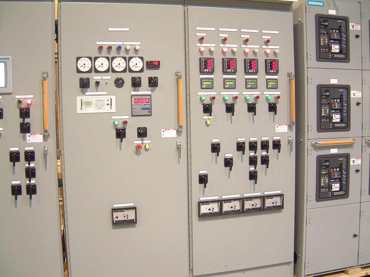
Power distribution, with purpose.
A factory electrical distribution expansion is more than adding breaker spaces. New production lines can increase load, change fault-current exposure, compete for limited electrical-room space and require connections during a narrow shutdown window. A sound plan ties the equipment selection to verified system data, the physical room and the sequence for keeping production safe and predictable.
Start with the room and the operating plan
Document the existing equipment lineup before selecting an extension or replacement. Record available wall and floor space, working clearances, door and aisle dimensions, ceiling height, cable trenches, overhead bus or conduit routes, and access from the receiving point to the electrical room. Check environmental conditions such as heat, dust, moisture and corrosive exposure. A lineup that fits on a one-line diagram may still be impractical if it blocks an exit, prevents maintenance access or cannot be moved through the building.
Production constraints deserve the same early attention. Identify which loads can be interrupted, how long each interruption can last, whether temporary power is feasible and who has authority to approve an outage. Determine whether the new equipment can be installed in a separate area and connected later, or whether existing gear must be modified. Those choices affect scope, interfaces and schedule risk; they should be settled with the facility’s electrical and operations teams before a quote is treated as a buildable design.
Verify load growth and future feeder needs
Build the expansion forecast from actual production plans rather than simply adding nameplate values. Gather existing demand data, transformer and service information, motor starting requirements, power-factor correction or harmonic concerns, and the planned loads for each new line. Identify which loads operate together and whether future shifts, process changes or added automation are likely. The electrical engineer can use this information to assess the system and define the required bus, main and feeder arrangements.
Reserve capacity only where it has a clear purpose. Spare breaker positions do not automatically mean the bus, upstream source or fault-current rating can support later loads. State the intended future feeders, their expected load characteristics and when they may be installed. System nominal voltage and equipment maximum rating are related but distinct; both, along with continuous current and short-circuit requirements, must be confirmed for the specific order and coordinated with the rest of the distribution system.


Coordinate interfaces, protection and installation
An expansion can touch the utility service, transformer, existing switchboard or switchgear, downstream panels, generator, UPS, controls and building systems. Provide current one-line diagrams and identify equipment that will remain, be replaced or be altered. Confirm connection points, phase sequence, grounding method, cable entry direction, lug or termination requirements, control voltage, metering needs and communication interfaces. Existing drawings may be outdated, so field verification by qualified personnel and engineering review are important before dimensions and interfaces are frozen.
Protection and physical fit must be evaluated together. Changes in source capacity or transformer configuration can affect available fault current and protective-device coordination. Specify the required interrupting or short-circuit ratings based on the system study, not an assumption that the old lineup’s rating carries over. For low-voltage switchboards, UL 891 may be applicable when specified and confirmed for the particular assembly. It is not a general listing for medium-voltage equipment, and standards or listed status should never be assumed without order-specific confirmation.
Illustrative scenario: a line addition under a tight outage
Consider a hypothetical food-processing factory adding a packaging line while keeping its existing distribution lineup in service. The room has one open wall, but a cable trench crosses the proposed equipment footprint, and the line must be connected during a scheduled maintenance shutdown. Operations wants the shortest interruption possible; maintenance needs accessible feeder breakers; engineering wants room for a later process expansion. These inputs point to a layout and tie-in plan that must be checked against actual room measurements and the existing system.
The team might compare a new adjacent lineup with a replacement lineup, considering footprint, outage duration, connection complexity, feeder access and the effect on production risk. An adjacent lineup may reduce disturbance to existing circuits but require careful coordination at the tie-in and more floor space. Replacing the lineup may create a cleaner arrangement but could demand a longer outage and broader reconnection scope. This is an example for planning discussion, not a completed project or a prescribed design.
Bring stakeholders and quote inputs together
A useful quote package reflects the people who will own, operate, approve and maintain the expansion. Facility engineering supplies system data and drawings; operations defines allowable shutdowns and startup priorities; maintenance identifies service preferences and access concerns; safety and facilities teams review room and egress constraints; and the electrical engineer or other authorized design professional establishes design criteria and approvals. Procurement should clarify required documentation, delivery destination, schedule expectations and any domestic-content or sourcing requirements.
For a new custom build, provide the one-line diagram, load and feeder schedule, available fault-current or study information, system voltage, required ratings, room dimensions, cable and bus interfaces, control and metering needs, environmental conditions, outage plan and target delivery window. The manufacturer builds and supplies new equipment, with American components and shorter lead time as goals rather than guarantees. Component availability, US-origin requirements, ratings, standards, assembly details and schedule must be validated for the specific order. Customers in Dallas–Fort Worth and elsewhere should confirm delivery and site-access assumptions with their project team.
Set approval boundaries before release
Keep design authority and manufacturing scope distinct. The purchaser’s engineer or other designated responsible professional must approve the system design, protection settings, fault-duty basis, interface details and code or utility requirements. The manufacturer can use the approved specifications to build the equipment, but a quote or drawing review does not replace the project engineer’s responsibility to verify suitability within the facility. Clarify who reviews submittals, resolves discrepancies and authorizes final production release.
Before approving the order, reconcile the equipment schedule, drawings, physical dimensions, feeder count, connection details and required documentation. Record assumptions and exclusions, especially where existing field conditions have not been verified. Final ratings, component availability, standards applicability, short-circuit capability and any US-origin criteria are order-specific. That discipline helps prevent a seemingly small factory expansion from becoming a room-fit problem, an avoidable shutdown extension or a mismatch with the existing distribution system.
Specifications & planning
Review the details that matter for your application. Final specifications and availability should be confirmed for your project.
| Evaluation factor | What to establish |
|---|---|
| Room capacity | Verified footprint, clearances, access path and cable routes |
| Production shutdown | Permitted interruption, tie-in sequence and outage approval owner |
| Future feeders | Planned circuits, load assumptions and intended growth horizon |
| System coordination | Source data, fault-duty basis and interfaces subject to engineering review |