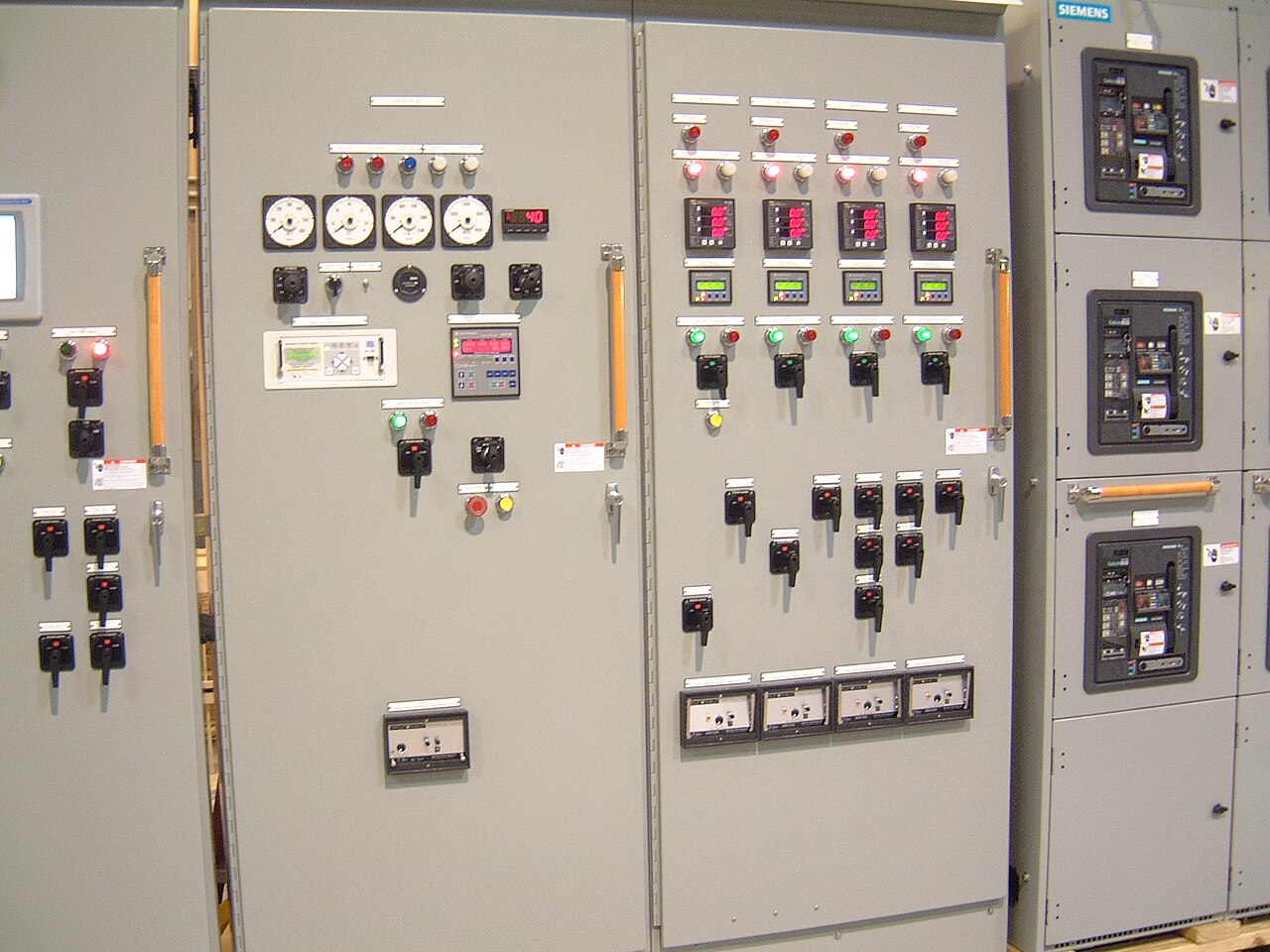
Power distribution, with purpose.
Industrial motor circuits can challenge switchgear at startup as well as during a fault. A sound design connects each motor’s starting method, operating duty, feeder protection, and upstream coordination instead of sizing around running horsepower alone. For manufacturing facilities, the goal is dependable operation without allowing a motor-starting event or a protective-device mismatch to create avoidable production interruptions.
Start with how each motor behaves
A motor’s nameplate horsepower is only one input to feeder selection. Engineers also need voltage, full-load current, locked-rotor or starting-current data, starting duration, starts per hour, load inertia, and the driven process. A loaded compressor, conveyor, pump, and fan can impose very different acceleration demands, even when their motors have similar ratings. The starting method matters too: across-the-line starting can produce a brief current several times full-load current, while reduced-voltage starters and variable-frequency drives change the current profile and the protective-device interfaces.
These characteristics affect conductor sizing, breaker or fuse selection, overload protection, and the switchboard’s bus and short-circuit ratings. A protective device must tolerate normal acceleration yet interrupt fault current within its rating and the equipment’s capabilities. Excessively sensitive settings can trip during a healthy start; overly permissive settings can undermine protection. Final decisions require the actual motor data, applicable electrical requirements, equipment ratings, and engineering review—not a rule of thumb based on horsepower.
Use coordination studies to test the design
A coordination study evaluates protective-device time-current behavior across the electrical system. For motor feeders, it should consider starting current and acceleration time alongside overload protection, short-circuit protection, upstream device curves, transformer characteristics, and available fault current. The study helps reveal whether a feeder device may open before an upstream device during a fault, or whether a motor’s normal start could cross a protective curve. Selective coordination is a design objective where required or specified, not an automatic property of any switchgear arrangement.
Study assumptions need to match the installation. Available fault current can vary with utility supply, transformers, generators, and system configuration; future changes can alter the results. Engineers should confirm device models and trip units, settings ranges, current-transformer data where relevant, and the intended operating modes. The study scope and acceptance criteria should be agreed by the responsible electrical engineer and owner. A manufacturer can use approved design inputs to develop equipment, but should not replace the engineer responsible for system studies or field verification.


Illustrative scenario: a loaded production line
Consider a hypothetical manufacturing line adding a large motor-driven compressor while an existing process motor remains in service. If both motors start close together, the combined demand could produce a voltage dip or nuisance operation, depending on the source strength, motor characteristics, and protection settings. The compressor’s load during acceleration also matters: a start under pressure may take longer than an unloaded start. These are planning questions, not evidence of a completed installation or a particular customer project.
The design team might compare sequencing starts, using a suitable reduced-voltage method, or changing the feeder and upstream protection arrangement. Each option has tradeoffs in controls, starting torque, equipment interfaces, and study results. A drive may limit starting current but introduce its own input protection, harmonics, bypass, and maintenance considerations. The preferred approach depends on process requirements and the engineer’s analysis; no single option guarantees acceptable voltage performance or coordination.
Bring the right stakeholders and documents
A useful quote package gives the manufacturer a defined electrical and mechanical scope. Purchasers should supply the one-line diagram, system nominal voltage, available fault-current information and source assumptions, motor schedule, motor starting method, feeder quantities, requested protection functions, control and metering needs, enclosure and environmental conditions, and connection details. Include the study’s device requirements or preliminary settings where available, plus applicable project specifications, drawings, and delivery constraints. Identify which information is confirmed and which remains preliminary.
The facility’s electrical engineer, controls team, operations staff, and procurement group each hold important inputs. Engineering defines system assumptions and approves protection and coordination; controls personnel clarify interlocks and start sequencing; operations explains production duty and acceptable interruption; procurement aligns scope, submittals, and schedule. For projects in Dallas–Fort Worth or elsewhere, these same technical inputs help avoid quote revisions regardless of delivery destination. Any interface with existing gear should be documented rather than inferred.
Balance protection, operability, and equipment scope
Selection involves more than choosing a breaker frame. A higher interrupting capability, adjustable trip functions, communications, metering, or a particular starter arrangement may affect footprint, cost, lead time, and integration work. A design with more adjustability can support study changes, but settings still need authorized engineering review and controlled documentation. Conversely, a compact or simplified arrangement may reduce complexity while limiting future flexibility. Confirm the required maintenance access, cable entry, spare feeder provisions, and control-power source before the layout is finalized.
Separate equipment decisions from field and study responsibilities. A manufacturer may build new custom switchgear using American components and can aim for a shorter lead time, subject to scope, component availability, and order review. Low-voltage switchboards may be designed as UL 891 assemblies when applicable; that standard does not apply as a general listing for medium-voltage gear. System nominal voltage, equipment maximum rating, short-circuit rating, standards, and any U.S.-origin requirements must be confirmed for the specific order. The responsible engineer and purchaser approve the design basis and final study; do not treat a quote as authorization to change field settings or energize equipment.
Specifications & planning
Review the details that matter for your application. Final specifications and availability should be confirmed for your project.
| Evaluation factor | Information to confirm |
|---|---|
| Motor duty | Starting current, acceleration time, load condition, and starts per hour |
| Protection basis | Device types, settings assumptions, and coordination-study criteria |
| System fault level | Available fault current, source configuration, and study date or assumptions |
| Equipment interface | Feeder count, controls, cable entry, and required ratings; subject to engineering review |