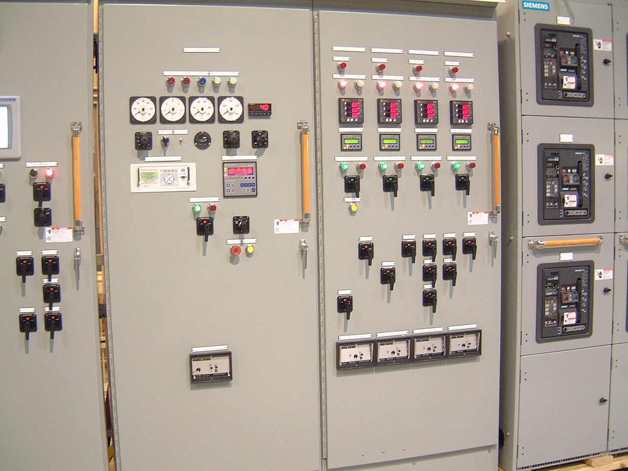
Power distribution, with purpose.
Hazardous-location interface planning starts with a boundary, not a product label: where a classified atmosphere may occur, what electrical equipment must connect across that boundary, and which authority will review the proposed arrangement. For oil and gas facilities, resolving those questions early helps prevent a switchboard or other assembly from being specified for a location its verified ratings do not cover.
Translate the area classification into placement decisions
The electrical area-classification documents should identify the applicable classification system, each classified area’s extent, and the conditions behind its designation. Under U.S. practice, that may include Class, Division, and Group information or Zone classification, as applicable. The responsible facility professionals establish and document the classification; a switchgear manufacturer should not infer it from a process description, equipment name, or a general statement such as “outdoor oil and gas service.”
Use the drawings to check the exact proposed equipment location, not just the room or process-unit name. A lineup may be outside a classified boundary while cable, conduit, control, or instrument interfaces cross into one. That can change enclosure, wiring method, sealing, separation, and termination decisions. If the boundary is unsettled or changes between drawings, identify the discrepancy for engineering review before requesting a firm equipment configuration.
Define the electrical and physical interfaces
A useful interface review follows each connection from the source through the assembly to the field load. Specify system nominal voltage and frequency separately from the equipment’s maximum voltage rating, then define bus and feeder requirements, available fault current, required short-circuit rating, grounding arrangement, and protection or metering functions. These values must be coordinated with the actual system and confirmed for the particular order; a nominal voltage alone does not establish a suitable interrupting or withstand capability.
Physical constraints matter as much as the one-line diagram. Provide the room or outdoor installation arrangement, access and egress limits, cable entry direction, conductor sizes and termination details, environmental conditions, and any required separation from classified equipment. State which party supplies transition boxes, seals, barriers, raceways, and field wiring. A clear responsibility boundary reduces the risk that an assembly is ordered with a connection method that conflicts with the facility’s approved hazardous-location design.


Separate assembly scope from hazardous-location approval
A low-voltage switchboard may be built as a UL 891 assembly when the specific design and order support that construction. UL 891 applies to low-voltage switchboards; it does not establish that equipment is suitable for a hazardous location, nor does it apply as a general listing for medium- or high-voltage switchgear. Where medium-voltage equipment is involved, identify the applicable equipment class, standards, ratings, and documentation separately rather than carrying over a low-voltage designation.
Approval boundaries should be explicit in the specification and submittal review. The manufacturer can confirm the equipment configuration, components, ratings, and documentation it can provide for a defined scope, subject to design review and availability. The owner’s electrical engineer, hazardous-area specialist, facility safety stakeholders, and authority having jurisdiction determine or review the classification and installation requirements within their respective roles. Do not treat a quote, drawing, or assembly standard as a substitute for required site approval.
Use stakeholder inputs to resolve open items
Before quote development, the purchaser should provide the latest one-line diagram, area-classification drawings and basis, equipment schedule, load and protection information, fault-current data, and project specifications. Include the installation location, environmental conditions, cable and conduit interface details, required control or communications points, and the intended review or approval pathway. Identify open engineering assumptions instead of presenting preliminary values as approved requirements.
The owner or operator, electrical engineer, process and safety representatives, EPC or design team, and equipment supplier may each hold different pieces of the interface. A short coordination review can establish who owns classification revisions, protection coordination, field connection design, and final acceptance. For projects serving Dallas–Fort Worth or elsewhere, delivery geography does not change the need for project-specific ratings and approvals; shipment planning should follow a configuration that has been reviewed against the site documents.
Compare tradeoffs without assuming suitability
One practical tradeoff is whether to place a standard assembly outside the classified boundary and route connections into the process area, or to place equipment closer to the load under a specifically reviewed design. Remote placement can simplify exposure concerns but may increase cable runs, voltage drop, coordination work, and space needs. Locating equipment nearer the load can reduce some interface distances while creating more demanding environmental and classification questions. Neither approach is inherently correct without the drawings, operating conditions, and responsible engineer’s review.
A custom new assembly can help coordinate incoming and outgoing sections, protective devices, metering, and project-specific interfaces in one build scope. American components may be requested, but component origin, availability, and any applicable domestic-content requirements must be confirmed for the specific order. A shorter lead time can be a planning goal, not a guarantee; late classification changes, component selection, and approval cycles can affect schedule. Confirm all ratings, standards, component availability, and U.S.-origin requirements before release.
Illustrative scenario: pause at a changing boundary
Consider a hypothetical compressor-station expansion where an early layout places a low-voltage switchboard in an electrical room, but a later process drawing shifts a classified-area boundary toward the room’s cable-entry side. The initial equipment schedule does not settle the issue: the team must reconcile the current classification drawing, the room arrangement, and the proposed cable route. The supplier should not declare the assembly suitable based on the earlier layout or on the facility type alone.
The project team can compare revised placement and routing options, confirm the applicable classification and installation details, and update the electrical specification before final configuration. For quote review, ask the manufacturer to identify its proposed assembly scope, stated ratings, component assumptions, and exclusions, then route those documents through the project’s engineering and approval process. This example is illustrative only, not a completed project or a claim of suitability for any particular hazardous location.
Specifications & planning
Review the details that matter for your application. Final specifications and availability should be confirmed for your project.
| Evaluation factor | Information to confirm |
|---|---|
| Area classification | Current classification system, boundary drawings, and responsible technical authority |
| Electrical duty | Nominal system voltage, equipment rating, available fault current, and required short-circuit rating |
| Interfaces | Cable entry, termination details, grounding, control points, and party responsible for field connections |
| Review boundary | Required engineering reviews, submittals, and authority having jurisdiction approval |