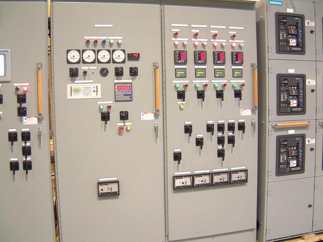
Power distribution, with purpose.
A busbar joint is only as dependable as the surfaces that meet and the procedure used to assemble them. Plating can influence contact behavior, corrosion resistance, wear, and compatibility with connected parts, but no finish is right for every design. For a new switchboard or busbar assembly, the useful starting point is the complete joint: conductor materials, current and fault requirements, environment, mating hardware, and the governing drawings and specifications. Those inputs let the design team evaluate the contact surface without assuming one plating or preparation method fits all applications.
Choose a finish for the whole joint
Copper busbars may use bare or plated contact areas depending on the electrical design, service environment, mating components, and applicable project requirements. Tin plating is commonly considered where a conductive, protective finish and compatibility with specified interfaces are important. Silver plating may be considered for particular contact designs, but its cost, exposure conditions, and compatibility with adjoining materials need review. These are options to assess, not a promise that a specific finish is available or appropriate for every order.
The selection should account for the full contact stack, not just the busbar drawing. A plated bar joined to a differently finished lug, device terminal, or connector can introduce material and interface questions that a one-part specification misses. The design review should identify which surfaces actually carry current, whether coatings are required on all faces or only contact zones, and how the finish affects clearances, fit, and assembly. Any required plating thickness, coverage, or finish standard must be stated or confirmed for the specific build.
Define contact surfaces and mating parts
A contact surface is the area intended to make electrical and mechanical contact after assembly. Its shape, flatness, dimensions, hole pattern, and relationship to adjacent insulation or hardware can matter as much as its nominal finish. Drawings should distinguish contact faces from edges or other surfaces, show the joint geometry, and identify the conductor and connecting component. If a device terminal or customer-supplied connector sets the interface, its manufacturer and part details help avoid assumptions about material, finish, or permissible assembly conditions.
Material combinations deserve particular attention where copper meets aluminum or where dissimilar finishes and hardware are involved. Oxidation, corrosion exposure, thermal cycling, and joint movement can affect long-term contact performance. The appropriate response may involve a specified transition component, surface finish, or approved joint design, but the choice depends on engineering review and the applicable equipment requirements. A fabrication quote should not silently substitute a different contact area, plating, or mating component because it appears dimensionally similar.


Match plating to the service environment
Indoor, controlled electrical rooms and locations exposed to condensation, industrial contaminants, salt-bearing air, or frequent temperature changes present different risks. The project description should state where the assembly will operate and whether unusual moisture, airborne chemicals, washdown, or outdoor exposure is expected. Plating can help address certain surface concerns, but it does not by itself make a joint suitable for every corrosive environment or replace enclosure, sealing, ventilation, or maintenance requirements.
Environmental choices also affect cost, sourcing, and schedule. More extensive coverage or a specialized finish may add process and inspection requirements, while a finish selected without considering the mating part can create a compatibility issue rather than solve one. For equipment serving customers in Dallas–Fort Worth or shipping elsewhere, the actual installation conditions matter more than the destination label: indoor service, outdoor exposure, and the surrounding process environment should be specified. Any U.S.-origin material or component requirement should be identified separately and confirmed for the order.
Use approved procedures, not generic torque advice
Joint assembly instructions should come from the approved equipment design, component manufacturer requirements, and applicable project documentation. Torque depends on details such as fastener size and grade, lubrication or coating, washer arrangement, thread condition, and the connected parts. A generic torque value or universal surface-preparation instruction can be unsafe or unsuitable when those conditions differ. The assembly team should work from the procedure approved for the particular joint rather than infer one from a different busbar design.
Surface preparation is likewise design- and finish-dependent. Requirements may address handling, cleanliness, protection from damage, and whether a plated surface is to remain untouched, but the allowed methods need explicit engineering approval. Uncontrolled abrasion, chemical cleaning, or coating removal can alter the contact surface and invalidate a specified finish. If the purchaser has a required joint procedure, reference it in the inquiry; otherwise, confirm how the applicable procedure, inspection points, and documentation will be established before release to fabrication.
Supply enough detail for a meaningful quote
For a quote, provide the current busbar and assembly drawings, conductor material and dimensions, joint locations, hole patterns, connected device or lug information, and the required electrical and mechanical ratings. Include the specified plating type, thickness or standard if known, coverage limits, finish on mating parts, and any environmental or corrosion requirements. Also identify the governing project specification, applicable standards, customer-approved procedures, and required inspection or record format. If a requirement is still under review, say so rather than presenting a preliminary selection as final.
These inputs let the manufacturer identify open technical questions before a new-build scope is fixed. A custom assembly may be developed around project-specific interfaces, and American components or a shorter lead time may be goals where the design and sourcing allow; neither component availability nor schedule is universal. Customers should distinguish system nominal voltage from equipment maximum rating and provide required continuous-current and short-circuit information for engineering review. Ratings, standards, and any U.S.-origin requirements must be confirmed for the specific order.
Make the approved design traceable
Before production, the useful drawing output is one that makes the joint unambiguous: conductor and mating-part materials, contact-face location, finish callout, dimensions, hardware interface, and applicable notes should agree across the assembly and component documents. Where plating coverage or a special interface is critical, a drawing detail or separate specification can prevent a broad finish note from being interpreted differently by purchasing, fabrication, and inspection. Open items should be resolved through documented engineering review rather than informal shop-floor assumptions.
The project record may identify the approved drawing revision, specified materials and finishes, inspection criteria, and the applicable assembly procedure or acceptance evidence. The exact records depend on the contract and agreed scope; they should not be assumed to include a particular test or certification unless specified and confirmed. Busbar plating and contact-surface work is one part of a complete electrical assembly, not a substitute for system design, field installation, or energized maintenance. Any unverified finish, process, or documentation capability should be validated before publication or commitment.
Specifications & planning
Review the details that matter for your application. Final specifications and availability should be confirmed for your project.
| Evaluation factor | Information to resolve |
|---|---|
| Conductor and mating materials | Busbar alloy and connected terminal or connector materials |
| Finish requirement | Plating type, coverage, thickness or governing specification |
| Service environment | Indoor or outdoor conditions, moisture, contaminants, and temperature exposure |
| Joint procedure and records | Approved assembly instructions, inspection criteria, and required documentation |